630 Draw The Shear And Moment Diagrams For The Beam
630 Draw The Shear And Moment Diagrams For The Beam - Shear and moment diagrams and formulas are excerpted from the western woods use book, 4th edition, and are provided herein as a courtesy of western wood products association. This is a very useful skill to be good at for statics and mechanics of materials. Start at one end, (point a), of the beam and work toward the other end. Web in this video we cover how to draw the shear and moment diagrams for a beam. Solve for all external forces and moments, create a free body diagram, and create the shear diagram. Draw the shear force, axial force and bending moment diagrams. Web in order to construct shear and moment diagrams for a beam, first, determine the reactive forces and couple moments acting on the beam, and resolve all the forces into components acting perpendicular and parallel to the beam’s axis. Lined up below the shear diagram, draw a set of axes. Draw the shear and moment diagrams for the beam. Assume that the flexural rigidity is a multiple of ei and differs for each member as shown in the figure.
Draw the shear and moment diagrams for the beam, and determine the shear and moment throughout the beam as functions of x. 100% (2 ratings) share share. The failure modes of the joint region and the overall steel frame structure under the action of the earthquake need to be studied. So in this post we’ll give you a thorough introduction to shear forces, bending moments and how to draw shear and moment diagrams. Neglect the mass of the beam in each problem. They allow us to see where the maximum loads occur so that we can optimize the design to prevent failures and reduce the overall weight and cost of the structure. We are required to draw the shear force and bending moment diagram for the given beam. Internal forces in beams and frames, libretexts. The forces and moment acting on the beam are: Here’s the best way to solve it.
Solve for all external forces and moments, create a free body diagram, and create the shear diagram. Start at one end, (point a), of the beam and work toward the other end. This is a very useful skill to be good at for statics and mechanics of materials. The failure modes of the joint region and the overall steel frame structure under the action of the earthquake need to be studied. First of all we need to find out the reactions with the help of equilibrium equations, σ v = 0. Mmax = 84 knm, σmax = 98.9 mpa. Determine the reactions at the supports using equilibrium equations. Web draw the shear and moment diagrams for the beam. The beginning, end, or change of a load pattern. Shear and moment diagrams and formulas are excerpted from the western woods use book, 4th edition, and are provided herein as a courtesy of western wood products association.

Brief Information About Shear Force And Bending Moment Diagrams
Web in this video we cover how to draw the shear and moment diagrams for a beam. Lined up below the shear diagram, draw a set of axes. V a + v b = 200 × 3 + 1 2 × 3 × 200 = 900 n. Web our calculator generates the reactions, shear force diagrams (sfd), bending moment diagrams.

Solved Draw the shear and moment diagrams for the beam
Total load = 10 + 8 + 6 = 24 k i p. Here’s the best way to solve it. Draw the shear force, axial force and bending moment diagrams. The failure modes of the joint region and the overall steel frame structure under the action of the earthquake need to be studied. Also, draw shear and moment diagrams, specifying.

Learn How To Draw Shear Force And Bending Moment Diagrams Engineering
Lined up below the shear diagram, draw a set of axes. First of all we need to find out the reactions with the help of equilibrium equations, σ v = 0. So in this post we’ll give you a thorough introduction to shear forces, bending moments and how to draw shear and moment diagrams. Web learn to draw shear force.
Solved Draw the shear and moment diagrams for the beam.
Web below is a simple example of what shear and moment diagrams look like, afterwards, the relation between the load on the beam and the diagrams will be discussed. Here’s the best way to solve it. Web our calculator generates the reactions, shear force diagrams (sfd), bending moment diagrams (bmd), deflection, and stress of a cantilever beam or simply supported.

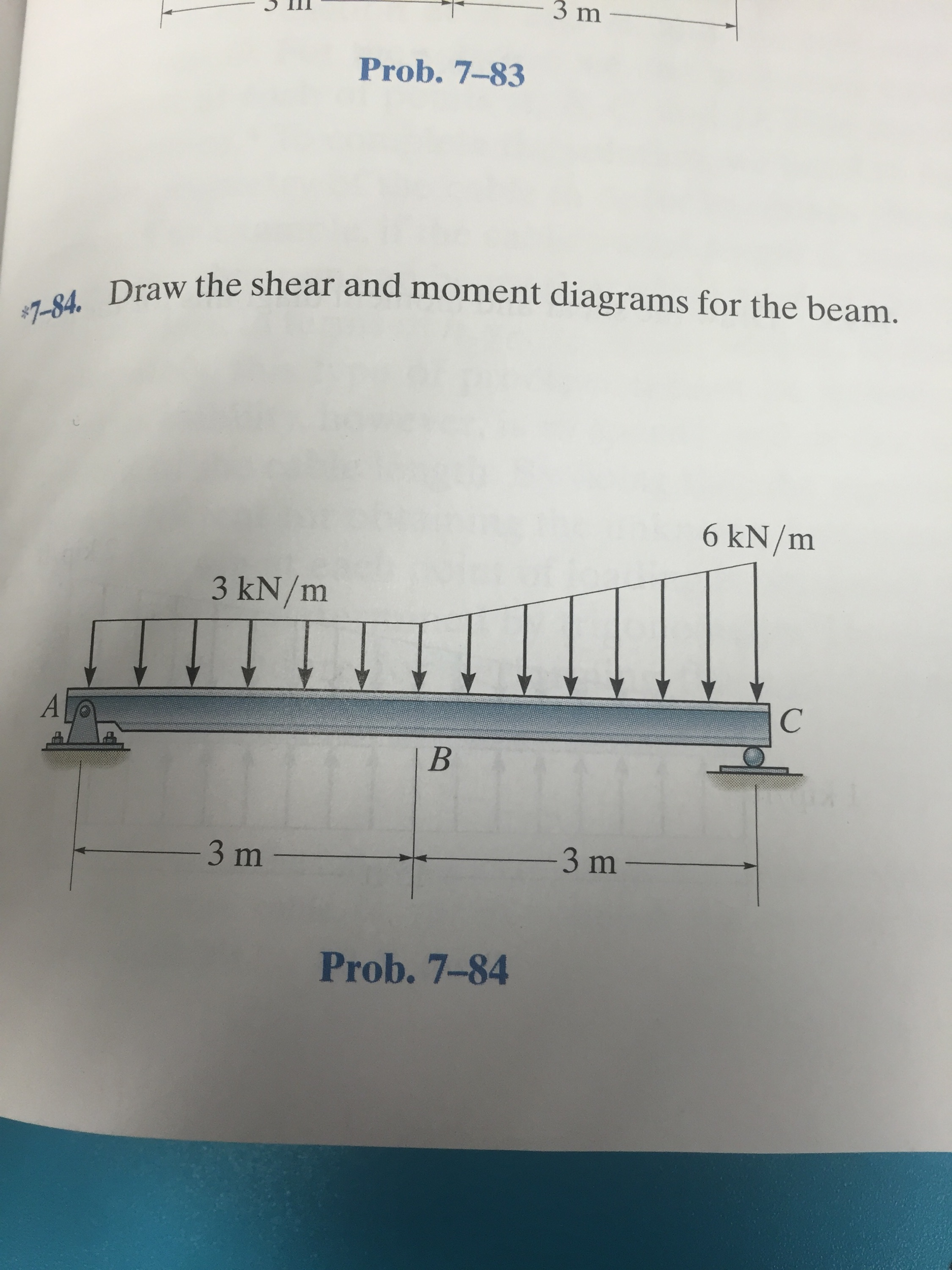
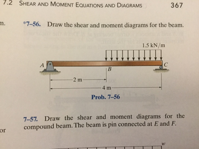
Draw the shear and moment diagrams for the beam.
The forces and moment acting on the beam are: This problem has been solved! Web the first step in calculating these quantities and their spatial variation consists of constructing shear and bending moment diagrams, \(v(x)\) and \(m(x)\), which are the internal shearing forces and bending moments induced in. The seismic performance of different types of weakened. Web our calculator generates.

Statics 7.71 Draw the shear and moment diagram for the beam. YouTube
Draw the shear and moment diagrams for the beam and determine the shear and moment in the beam as functions of x , where x is greater than 4ft and less. Web draw the shear and moment diagrams for the beam. Determine the reactions at the supports using equilibrium equations. The seismic performance of different types of weakened. Shear and.

Shear and moment diagrams geekloki
F 1 = 800n f 2 = 600n m = 1200n⋅m. The seismic performance of different types of weakened. They allow us to see where the maximum loads occur so that we can optimize the design to prevent failures and reduce the overall weight and cost of the structure. Write answers in the space provided. Lined up below the shear.

Solved Draw the shear and moment diagrams for the beam.
Therefore, view the full answer step 2. Web figures 1 through 32 provide a series of shear and moment diagrams with accompanying formulas for design of beams under various static loading conditions. Internal forces in beams and frames, libretexts. Write shear and moment equations for the beams in the following problems. Web to create the moment diagram for a shaft,.
draw the shear and moment diagrams for the beam chegg
Shear and bending moment equations. Civil engineering questions and answers. B a a a prob. The seismic performance of different types of weakened. Mmax = 84 knm, σmax = 98.9 mpa.

Shear Force and Bending Moment diagram of Beam with Triangular Load
F 1 = 800n f 2 = 600n m = 1200n⋅m. Write answers in the space provided. They allow us to see where the maximum loads occur so that we can optimize the design to prevent failures and reduce the overall weight and cost of the structure. Civil engineering questions and answers. Internal forces in beams and frames, libretexts.
Web The First Step In Calculating These Quantities And Their Spatial Variation Consists Of Constructing Shear And Bending Moment Diagrams, \(V(X)\) And \(M(X)\), Which Are The Internal Shearing Forces And Bending Moments Induced In.
Skyciv beam tool guides users along a professional beam calculation workflow, culminating in the ability to view and determine if they comply with your region's design codes. Draw the shear and moment diagrams for the beam. Lined up below the shear diagram, draw a set of axes. Draw the shear and moment diagrams for the compound beam.
Write Answers In The Space Provided.
480 views 4 months ago chapter 6 (bending) by mechanics of materials r.c hibbeler (9th edition), complete solution by engr adnan rasheed mechanical. We are required to draw the shear force and bending moment diagram for the given beam. Write shear and moment equations for the beams in the following problems. The failure modes of the joint region and the overall steel frame structure under the action of the earthquake need to be studied.
Web To Create The Moment Diagram For A Shaft, We Will Use The Following Process.
We go through breaking a beam into segments, and then we learn about the relationships between shear force. Also, draw shear and moment diagrams, specifying values at all change of loading positions and at points of zero shear. 100% (2 ratings) share share. In each problem, let x be the distance measured from left end of the beam.
Civil Engineering Questions And Answers.
Internal forces in beams and frames, libretexts. Web ay this will allow you to find external ex bx' bx' bx bx by' by' by by cy ey reaction forces at the supports and internal reaction forces at the hinge. Web the quickest way to tell a great cv writer from a great graduate engineer is to ask them to sketch a qualitative bending moment diagram for a given structure and load combination! This is an example problem that will show you how to graphically draw a shear and moment diagram for a beam.