753 Draw The Shear And Moment Diagrams For The Beam
753 Draw The Shear And Moment Diagrams For The Beam - Advanced physics questions and answers. − 6 × 9 1. Since δx δ x is infinitely narrow, we can assume that the distributed load over this small distance is constant and equal to the value at x, x, and call it w. Web ay this will allow you to find external ex bx' bx' bx bx by' by' by by cy ey reaction forces at the supports and internal reaction forces at the hinge. The beginning, end, or change of a load pattern. Draw the shear and moment diagrams for the beam.problem from engineering mechanics statics, fifteenth edition. Web mechanical engineering questions and answers. Also, draw shear and moment diagrams, specifying values at all change of loading positions and at points of zero shear. Web the first step in calculating these quantities and their spatial variation consists of constructing shear and bending moment diagrams, \(v(x)\) and \(m(x)\), which are the internal shearing forces and bending moments induced in. This is an example problem that will show you how to graphically draw a shear and moment diagram for a beam.
Shear and bending moment equations. Problem 7.53 draw the shear and moment diagrams for the beam. Web in order to construct shear and moment diagrams for a beam, first, determine the reactive forces and couple moments acting on the beam, and resolve all the forces into components acting perpendicular and parallel to the beam’s axis. Draw the shear and moment diagrams for the beam.problem from engineering mechanics statics, fifteenth edition. Click on add discontinuity to add discontinuity lines. Draw the shear and moment diagrams for the beam, and determine the shear and moment throughout the beam 10 kip 2 kip/ft g kip 8 kip 40 kip.ft as functions of x. You'll get a detailed solution from a subject matter expert that helps you learn core concepts. Web shear and moment diagrams are graphs which show the internal shear and bending moment plotted along the length of the beam. 92k views 3 years ago statics. Problem 7.53 draw the shear diagram for the beam.
Web shear and moment diagrams are graphs which show the internal shear and bending moment plotted along the length of the beam. Web you will be fully competent in drawing shear force and bending moment diagrams for statically determinate beams and frames. Applying the force equilibrium in the vertical direction gives the following result: Write shear and moment equations for the beams in the following problems. Shear and moment diagrams and formulas are excerpted from the western woods use book, 4th edition, and are provided herein as a courtesy of western wood products association. Draw the shear and moment diagrams for the beam. The reactions shown on the diagram are determined from equilibrium equations as follows: Civil engineering questions and answers. In general the process goes like this:. This problem has been solved!

Brief Information About Shear Force And Bending Moment Diagrams
Mechanical engineering questions and answers. They allow us to see where the maximum loads occur so that we can optimize the design to prevent failures and reduce the overall weight and cost of the structure. Since δx δ x is infinitely narrow, we can assume that the distributed load over this small distance is constant and equal to the value.

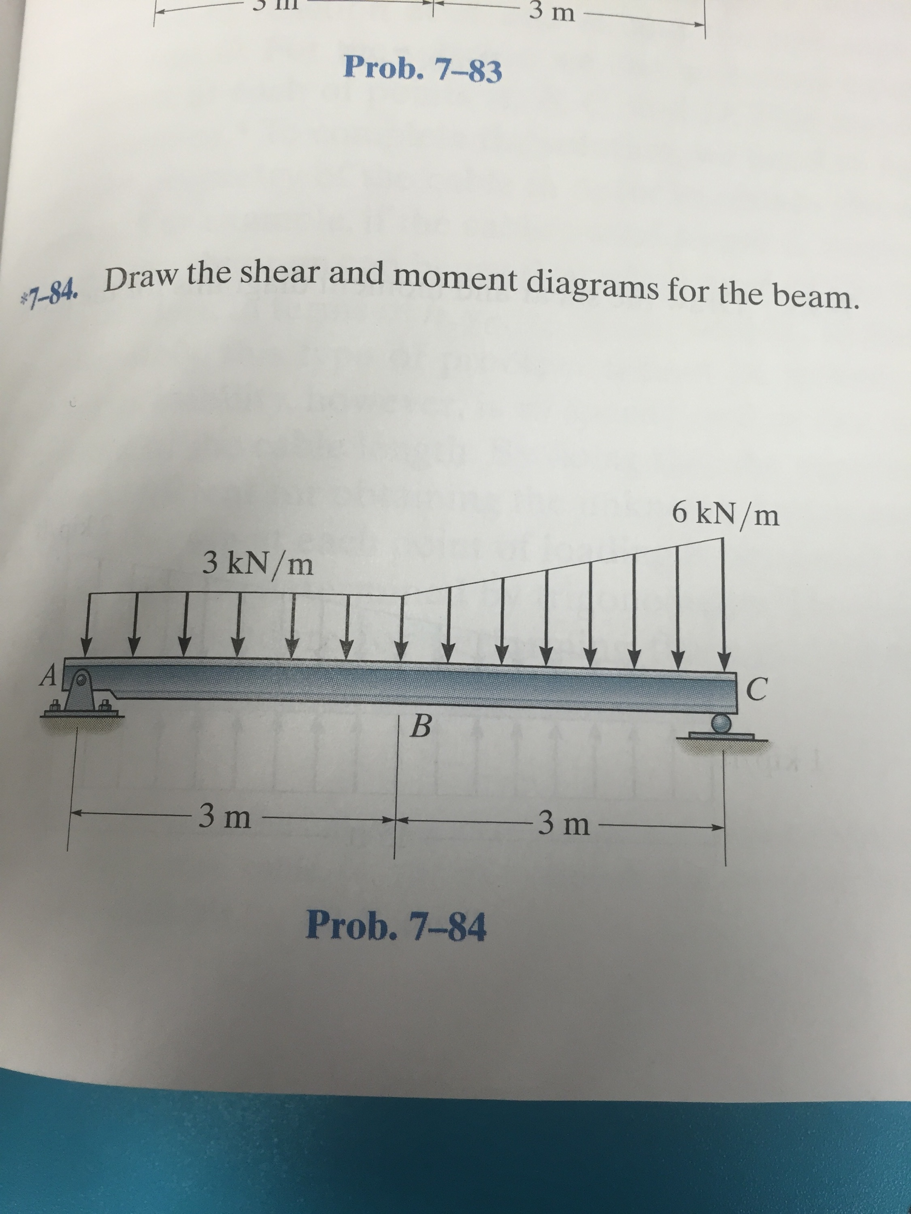
Draw the shear and moment diagrams for the beam.
Draw the shear and moment diagrams for the beam.problem from engineering mechanics statics, fifteenth edition. 20 kn 40 kn/m cl 150 kn m 8 m 3 m prob. Web write equations for the shear v and bending moment m for any section of the beam in the interval ab. Section the beam at points near supports and load application points..

Shear Force and Bending Moment diagram of Beam with Triangular Load
Shear and bending moment equations. Web ay this will allow you to find external ex bx' bx' bx bx by' by' by by cy ey reaction forces at the supports and internal reaction forces at the hinge. Draw the shear force, axial force and bending moment diagrams. Also, draw shear and moment diagrams, specifying values at all change of loading.

Shear force and bending moment diagrams for beams pdf
Draw the shear and moment diagrams for the beam. 20 kn 40 kn/m cl 150 kn m 8 m 3 m prob. (9) 9 × 0 2 3 ∴ r = 9 kn. Web in order to construct shear and moment diagrams for a beam, first, determine the reactive forces and couple moments acting on the beam, and resolve all.

Learn How To Draw Shear Force And Bending Moment Diagrams Engineering
(45in.) 100 lb(15in.) 250 lb(20 in.) 100 lb(55in.) 0r 200 lbre fryc 0: Web in order to construct shear and moment diagrams for a beam, first, determine the reactive forces and couple moments acting on the beam, and resolve all the forces into components acting perpendicular and parallel to the beam’s axis. Applying the force equilibrium in the vertical direction.
Solved Draw the shear and moment diagrams for the beam.
You'll get a detailed solution from a subject matter expert that helps you learn. You will have a robust system of analysis that allows you to confidently tackle the analysis of. Draw the shear and moment diagrams for the | chegg.com. Advanced physics questions and answers. This problem has been solved!

Shear and moment diagrams geekloki
Civil engineering questions and answers. 20 kn 40 kn/m cl 150 kn m 8 m 3 m prob. Assume that the flexural rigidity is a multiple of ei and differs for each member as shown in the figure. Web in order to construct shear and moment diagrams for a beam, first, determine the reactive forces and couple moments acting on.

Solved Draw the shear and moment diagrams for the beam.
Advanced physics questions and answers. 42k views 2 years ago statics. Draw the shear and moment diagrams for the beam, and determine the shear and moment throughout the beam 10 kip 2 kip/ft g kip 8 kip 40 kip.ft as functions of x. Draw the shear and moment diagrams for the | chegg.com. You will have a robust system of.
draw the shear and moment diagrams for the beam chegg
In general the process goes like this:. Divide the beam (of length l) into n segments. 92k views 3 years ago statics. You'll get a detailed solution from a subject matter expert that helps you learn. Write answers in the space provided.

Learn How To Draw Shear Force And Bending Moment Diagrams Engineering
(draw them on these pages, below) 40 kn/m 8 m 3 m 150 knm a. Internal forces in beams and frames, libretexts. You will have a robust system of analysis that allows you to confidently tackle the analysis of. Web mechanical engineering questions and answers. Advanced physics questions and answers.
200Lb 100Lb 250Lb 100Lb 0 250 Lbrc
Civil engineering questions and answers. Web below is a simple example of what shear and moment diagrams look like, afterwards, the relation between the load on the beam and the diagrams will be discussed. You'll get a detailed solution from a subject matter expert that helps you learn core concepts. Write answers in the space provided.
Once These Are Determined, Derive The Shear And Moment Functions.
20 kn 40 kn/m cl 150 kn m 8 m 3 m prob. Draw the shear and moment diagrams for the | chegg.com. Web shear and moment diagrams are graphs which show the internal shear and bending moment plotted along the length of the beam. (draw them on these pages, below) 40 kn/m 8 m 3 m 150 knm a.
Web You Will Be Fully Competent In Drawing Shear Force And Bending Moment Diagrams For Statically Determinate Beams And Frames.
92k views 3 years ago statics. The beginning, end, or change of a load pattern. Draw the shear and moment diagrams for the beam. In general the process goes like this:.
− 6 × 9 1.
Shear and bending moment equations. Draw the shear and moment diagrams for the beam. Mmax = 84 knm, σmax = 98.9 mpa. Draw the shear force, axial force and bending moment diagrams.