Draw A Series Circuit
Draw A Series Circuit - This physics tutorial explains how to draw a series circuit made up of a lamp and a battery. The electrical connection is not branched in any way and any disruption of the circuit causes the entire circuit to lose current. Web problem solving strategies for series and parallel resistors. Draw a clear circuit diagram, labeling all resistors and voltage sources. An ammeter and a voltmeter is also included to measure the curre. Discover how voltage remains constant between elements and how current remains constant throughout the circuit. This step includes a list of the known values for the problem, since they are labeled in your circuit diagram. Record the number on the circuit diagram. Example of a series circuit with multiple components. Identify exactly what needs to be determined in the problem (identify the unknowns).
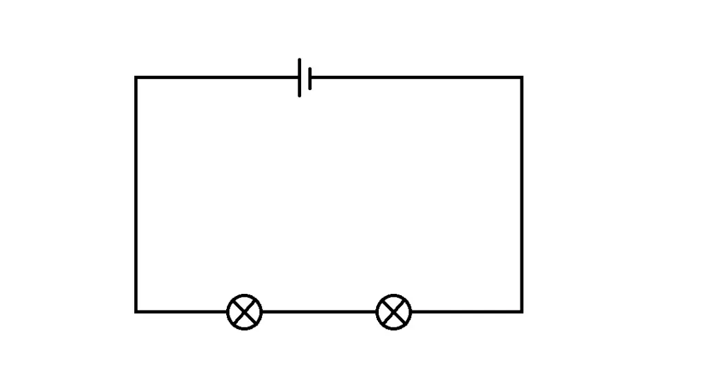
As mentioned in the previous section of lesson 4, two or more electrical devices in a circuit can be connected by series connections or by parallel connections. Web a circuit in series only has one loop that can be drawn throughout. Without changing the settings, allow the simulation to run for 20 s while you count the number of electrons passing through that spot. Identify exactly what needs to be determined in the problem (identify the unknowns). An ammeter and a voltmeter is also included to measure the curre. In a series circuit, each device is connected in a manner. Web problem solving strategies for series and parallel resistors. Explore the fundamentals of circuits and ohm's law with a focus on series circuits. Now pick three spots along the wire. Record the number on the circuit diagram.
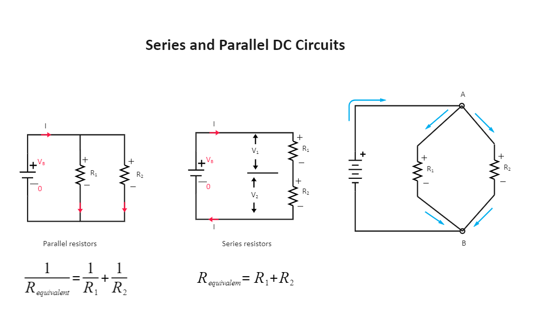
Draw a clear circuit diagram, labeling all resistors and voltage sources. Record the number on the circuit diagram. The total resistance in a series circuit is equal to the sum of the individual resistors, and the total voltage drop is equal to the sum of the individual voltage drops across those resistors. Learn how resistors in series increase total resistance, and how to calculate current using ohm's law. Draw a clear circuit diagram, labeling all resistors and voltage sources. An ammeter and a voltmeter is also included to measure the curre. This step includes a list of the knowns for the problem, since they are labeled in your circuit diagram. As mentioned in the previous section of lesson 4, two or more electrical devices in a circuit can be connected by series connections or by parallel connections. Now pick three spots along the wire. This step includes a list of the known values for the problem, since they are labeled in your circuit diagram.
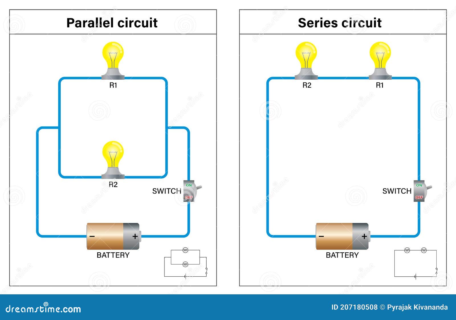
Series Circuit and Parallel Circuit Switch on Diagram Stock Vector
Explore the fundamentals of circuits and ohm's law with a focus on series circuits. Understanding series circuits is essential for anyone interested in electronics or physics, as they are the building blocks for more complex designs. An ammeter and a voltmeter is also included to measure the curre. In a series circuit, each device is connected in a manner. Draw.
.JPG)
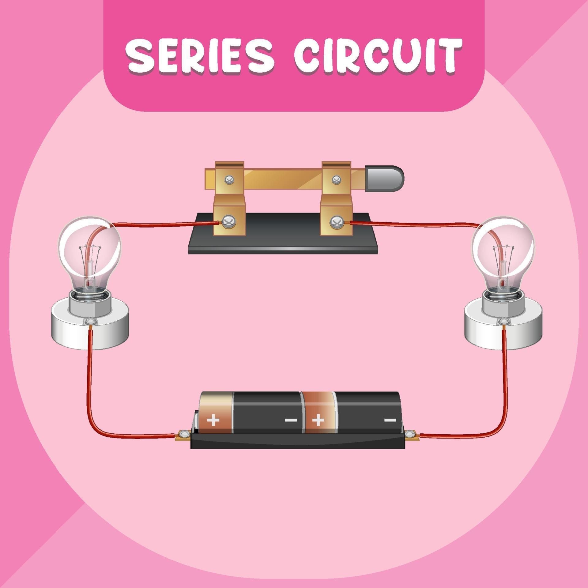
What is Series Circuit? « Electrical and Electronic Free Learning Tutorials
Identify exactly what needs to be determined in the problem (identify the unknowns). Without changing the settings, allow the simulation to run for 20 s while you count the number of electrons passing through that spot. Understanding series circuits is essential for anyone interested in electronics or physics, as they are the building blocks for more complex designs. Draw a.
Series Circuit Diagram EdrawMax Template
Example of a series circuit with multiple components. Now pick three spots along the wire. Learn how resistors in series increase total resistance, and how to calculate current using ohm's law. Web a circuit in series only has one loop that can be drawn throughout. Web draw the circuit diagram for the circuit, being sure to draw an arrow indicating.
Diagram For Series Circuit
Now pick three spots along the wire. Draw a clear circuit diagram, labeling all resistors and voltage sources. This physics tutorial explains how to draw a series circuit made up of a lamp and a battery. Understanding series circuits is essential for anyone interested in electronics or physics, as they are the building blocks for more complex designs. Explore the.
Example Of Series Circuit Diagram
This step includes a list of the knowns for the problem, since they are labeled in your circuit diagram. Web problem solving strategies for series and parallel resistors. Explore the fundamentals of circuits and ohm's law with a focus on series circuits. Draw a clear circuit diagram, labeling all resistors and voltage sources. When all the devices are connected using.
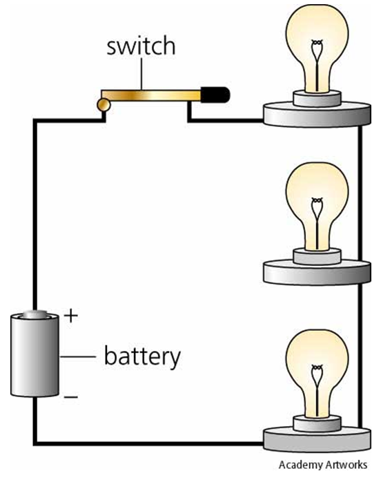
Diagram Of A Series Circuit
An ammeter and a voltmeter is also included to measure the curre. Explore the fundamentals of circuits and ohm's law with a focus on series circuits. The electrical connection is not branched in any way and any disruption of the circuit causes the entire circuit to lose current. When all the devices are connected using series connections, the circuit is.
Simple Series Circuit Diagram
Draw a clear circuit diagram, labeling all resistors and voltage sources. Understanding series circuits is essential for anyone interested in electronics or physics, as they are the building blocks for more complex designs. As mentioned in the previous section of lesson 4, two or more electrical devices in a circuit can be connected by series connections or by parallel connections..
Series Circuit Definition Series Circuit Examples Electrical Academia
The electrical connection is not branched in any way and any disruption of the circuit causes the entire circuit to lose current. This physics tutorial explains how to draw a series circuit made up of a lamp and a battery. Identify exactly what needs to be determined in the problem (identify the unknowns). Understanding series circuits is essential for anyone.

Different Types of Series Circuit Diagrams Explained(AC, DC) ETechnoG
Draw a clear circuit diagram, labeling all resistors and voltage sources. This physics tutorial explains how to draw a series circuit made up of a lamp and a battery. Identify exactly what needs to be determined in the problem (identify the unknowns). Explore the fundamentals of circuits and ohm's law with a focus on series circuits. Web problem solving strategies.
Pictorial Diagram Of Series Circuit
When all the devices are connected using series connections, the circuit is referred to as a series circuit. Draw a clear circuit diagram, labeling all resistors and voltage sources. Web a circuit in series only has one loop that can be drawn throughout. Understanding series circuits is essential for anyone interested in electronics or physics, as they are the building.
This Physics Tutorial Explains How To Draw A Series Circuit Made Up Of A Lamp And A Battery.
Web a circuit in series only has one loop that can be drawn throughout. Web draw the circuit diagram for the circuit, being sure to draw an arrow indicating the direction of the current. Identify exactly what needs to be determined in the problem (identify the unknowns). The electrical connection is not branched in any way and any disruption of the circuit causes the entire circuit to lose current.
Draw A Clear Circuit Diagram, Labeling All Resistors And Voltage Sources.
Discover how voltage remains constant between elements and how current remains constant throughout the circuit. Explore the fundamentals of circuits and ohm's law with a focus on series circuits. In a series circuit, each device is connected in a manner. Draw a clear circuit diagram, labeling all resistors and voltage sources.
Record The Number On The Circuit Diagram.
Web problem solving strategies for series and parallel resistors. Now pick three spots along the wire. Example of a series circuit with multiple components. An ammeter and a voltmeter is also included to measure the curre.
The Total Resistance In A Series Circuit Is Equal To The Sum Of The Individual Resistors, And The Total Voltage Drop Is Equal To The Sum Of The Individual Voltage Drops Across Those Resistors.
This step includes a list of the known values for the problem, since they are labeled in your circuit diagram. As mentioned in the previous section of lesson 4, two or more electrical devices in a circuit can be connected by series connections or by parallel connections. Without changing the settings, allow the simulation to run for 20 s while you count the number of electrons passing through that spot. Understanding series circuits is essential for anyone interested in electronics or physics, as they are the building blocks for more complex designs.