Draw Series Circuit
Draw Series Circuit - Divide the class into teams of four, having each team member number off so each has a different number, one. Because the circuit has three resistances, we only need to keep three terms, so it takes the form. Web adding more components to a series circuit increases the total resistance in the circuit, so less current flows. Explore the fundamentals of circuits and ohm's law with a focus on series circuits. Impedance calculation in rl series circuit example 1. Those five guys got outscored by 10 points in the span of 2 minutes, 21 seconds to start. The unknown is the voltage of the battery. Web foster was the crew chief for game 4 of the timberwolves playoff series with the phoenix suns and the two teams combined for 53 fouls after averaging 45.6 fouls in the first three games of the. Now according to ohm’s law, the voltage drop across resistor r 1, v 1 = ir 1. The total resistance of a series circuit is equal to the sum of the individual resistances.
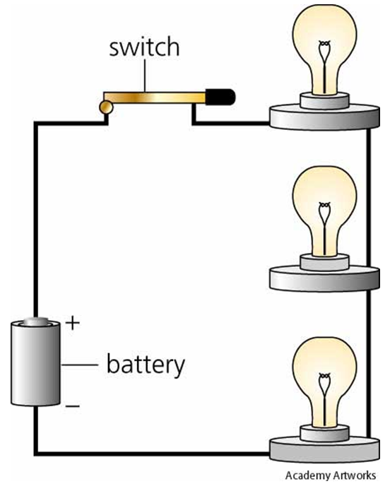
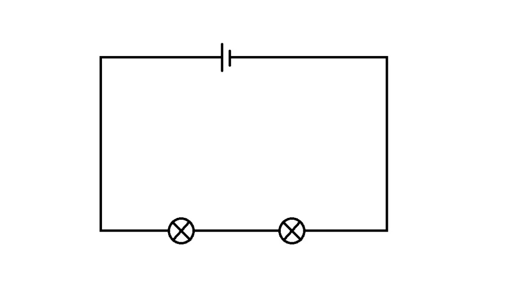
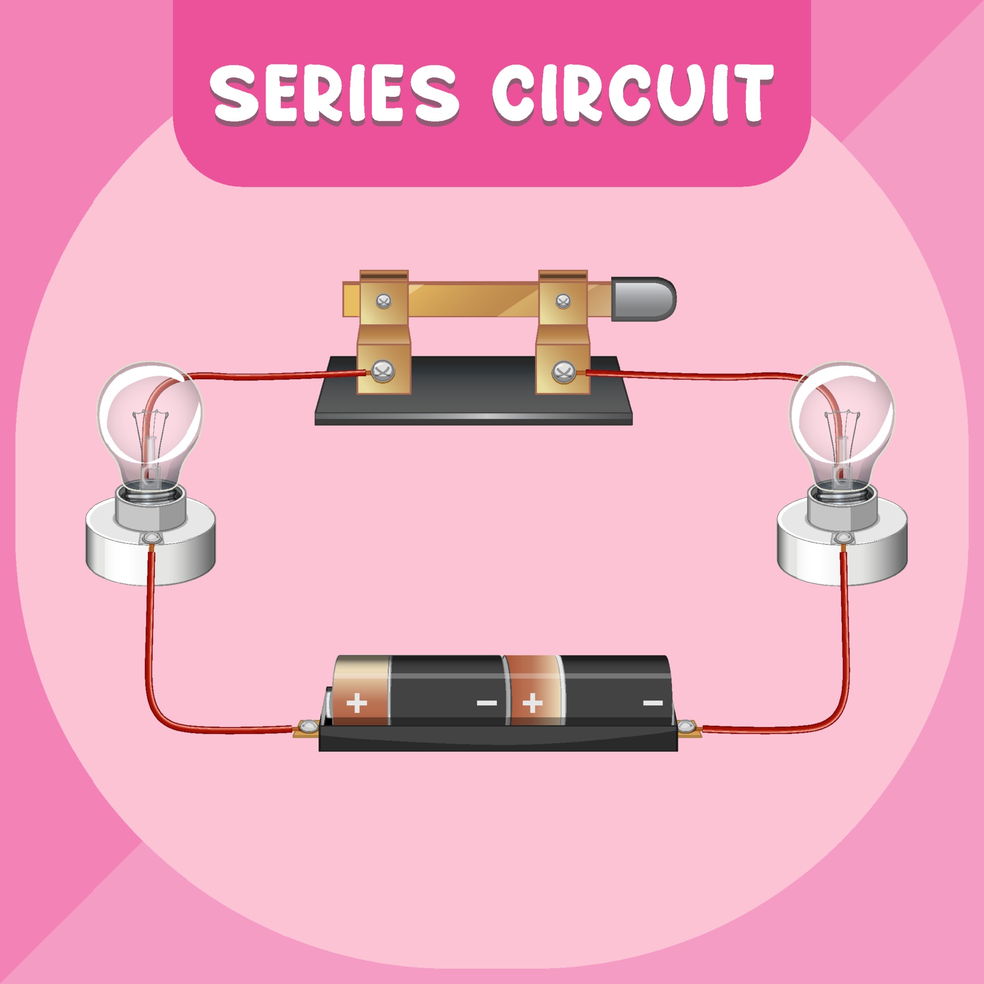
As mentioned in the previous section of lesson 4, two or more electrical devices in a circuit can be connected by series connections or by parallel connections. R equiv = r 1. Steps to draw a phasor diagram. Web foster was the crew chief for game 4 of the timberwolves playoff series with the phoenix suns and the two teams combined for 53 fouls after averaging 45.6 fouls in the first three games of the. An example of a series circuit. Web draw a circuit diagram of a series circuit with two batteries and three light bulbs. Record the readings in the table below. It should look like figure 4 with the switch replaced with a second battery.) figure drawing race: Web draw the circuit diagram for the circuit, being sure to draw an arrow indicating the direction of the current. Those five guys got outscored by 10 points in the span of 2 minutes, 21 seconds to start.
Steps to draw a phasor diagram. When all the devices are connected using series connections, the circuit is referred to as a series circuit. Those five guys got outscored by 10 points in the span of 2 minutes, 21 seconds to start. Impedance calculation in rl series circuit example 1. Web introduction to series circuits—a series circuit example. Web this guide covers series rc circuit analysis, its phasor diagram, power & impedance triangle, and several solved examples. The current through the circuit can be found from ohm’s law and is equal to the voltage divided by the equivalent resistance. The total voltage drop in a series circuit equals the sum. Web draw the circuit diagram for the circuit, being sure to draw an arrow indicating the direction of the current. The resistors in this circuit are arranged through straight lines, and are not cut off from each other.
Series Circuit Diagram Worksheets
Web resistors in series and parallel; Web the phasor diagram of the rc series circuit is shown below: Recall that current and voltage are in phase for purely resistive ac circuits, while current leads voltage by 90 degrees in purely capacitive circuits.therefore, when resistance and capacitance are combined, the overall. An example of a series circuit. Web in a series.
Simple Series Circuit Diagram
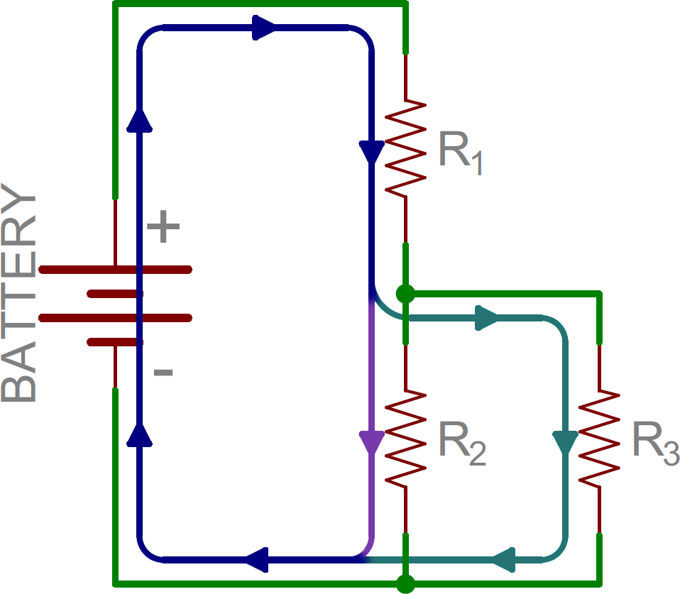
Web a series circuit in which the resistance is combined through the equation, rtotal = r1 + r2 +r3 +. Suppose three resistors r 1, r 2, and r 3 are connected in series across a voltage source of v (quantified as volts) as shown in the figure. Those five guys got outscored by 10 points in the span of.

How To Draw Series Circuit Diagrams
Calculate the impedance and the phase angle theta (θ) of the circuit. Web series rlc circuit example no1. The circuit on the left contains a lamp, a cell, a switch, and an ammeter. Web take a look at racing insights' latest cup series playoff projections as the circuit shifts to darlington raceway on sunday. Web a series circuit with a.
Series and Parallel Circuits SparkFun Learn
Explore the fundamentals of circuits and ohm's law with a focus on series circuits. Now according to ohm’s law, the voltage drop across resistor r 1, v 1 = ir 1. Because the circuit has three resistances, we only need to keep three terms, so it takes the form. Ohm’s law says the first resistor is still going to draw.
Series Parallel Circuit Series Parallel Circuit Examples Electrical
Draw a clear circuit diagram (figure \(\pageindex{8}\)). Web in this introduction to series resistance circuits, we will explain these three key principles you should understand:. A series rlc circuit containing a resistance of 12ω, an inductance of 0.15h and a capacitor of 100uf are connected in series across a 100v, 50hz supply. Web foster was the crew chief for game.
How To Draw Series Circuit Diagrams
Ohm’s law says the first resistor is still going to draw 1ma. Web in a series circuit, the equivalent resistance is the algebraic sum of the resistances. Calculate the total circuit impedance, the circuits current, power factor and draw the voltage phasor diagram. Determine if everyday objects are conductors or insulators, and take measurements with an ammeter and voltmeter. When.

Images Of Series And Parallel Circuit Diagrams Zoya Circuit
Record the readings in the table below. Learn how resistors in series increase total resistance, and how to calculate current using ohm's law. When all the devices are connected using series connections, the circuit is referred to as a series circuit. Web this physics tutorial explains how to draw a series circuit made up of a lamp and a battery..
How To Calculate A Series Parallel Circuit Wiring View and Schematics
An example of a series circuit. Web the phasor diagram of the rc series circuit is shown below: Ohm’s law says the first resistor is still going to draw 1ma. Web in a series rlc circuit there becomes a frequency point were the inductive reactance of the inductor becomes equal in value to the capacitive reactance of the capacitor. Web.
Series circuit infographic diagram 3093702 Vector Art at Vecteezy
As mentioned in the previous section of lesson 4, two or more electrical devices in a circuit can be connected by series connections or by parallel connections. Web resistors in series and parallel; Recall that current and voltage are in phase for purely resistive ac circuits, while current leads voltage by 90 degrees in purely capacitive circuits.therefore, when resistance and.

Different Types of Series Circuit Diagrams Explained(AC, DC) ETechnoG
Web the phasor diagram of the rc series circuit is shown below: Web introduction to series circuits—a series circuit example. Write the circuit symbols on the board. Web step 1 : Let current i (quantified as ampere) flow through the series circuit.
Web Series Dc Circuit Example.
As mentioned in the previous section of lesson 4, two or more electrical devices in a circuit can be connected by series connections or by parallel connections. An ammeter and a voltmeter is also included to measure the curre. Web draw a circuit diagram of a series circuit with two batteries and three light bulbs. Web resistors in series and parallel;
The Circuit On The Left Contains A Lamp, A Cell, A Switch, And An Ammeter.
View the circuit as a schematic diagram, or switch to a lifelike view. Recall that current and voltage are in phase for purely resistive ac circuits, while current leads voltage by 90 degrees in purely capacitive circuits.therefore, when resistance and capacitance are combined, the overall. The total resistance of a series circuit is equal to the sum of the individual resistances. Voltage drop in resistance vr = ir is taken in phase with the current vector;
Discover How Voltage Remains Constant Between Elements And How Current Remains Constant Throughout The Circuit.
But, so is the second resistor, and. In a series circuit, each device is connected in a manner. Connect the voltmeter in parallel with the cell. Web draw the circuit diagram for the circuit, being sure to draw an arrow indicating the direction of the current.
Web Series Rlc Circuit Example No1.
Each resistor in a series circuit shares one. Now according to ohm’s law, the voltage drop across resistor r 1, v 1 = ir 1. Draw a phasor diagram for given circuit. Web in a series circuit, the equivalent resistance is the algebraic sum of the resistances.