Draw Shear And Moment Diagram
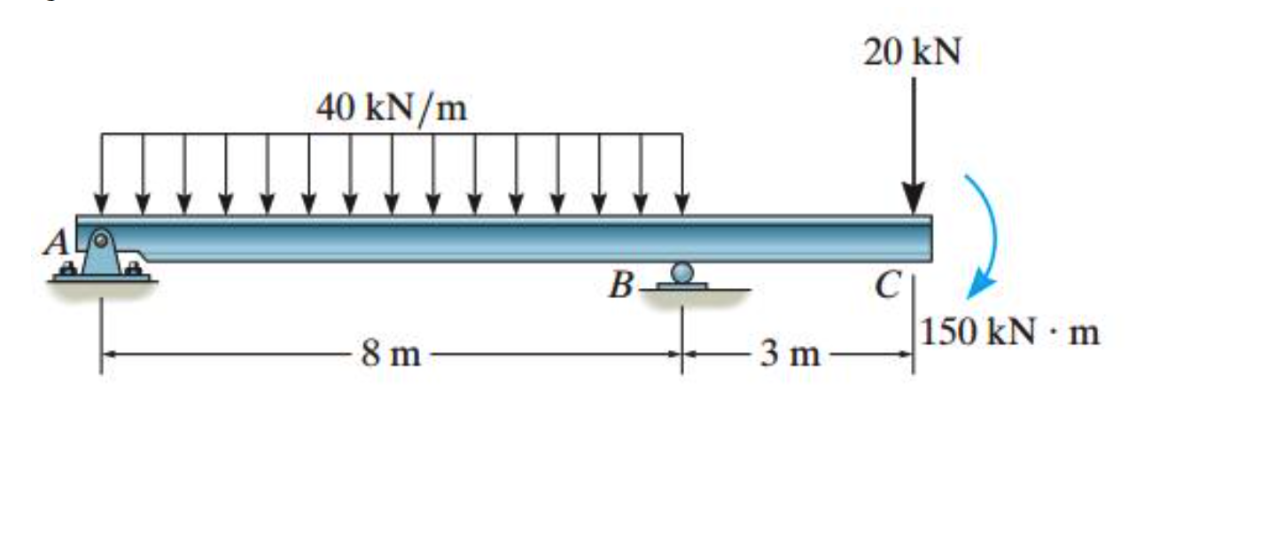
Draw Shear And Moment Diagram - Draw a fbd of the structure. Draw a free body diagram of the beam with global coordinates (x); There are 4 steps to solve this one. You'll get a detailed solution from a subject matter expert that helps you learn core concepts. Web step 1 | draw a free body diagram. Shear/moment diagrams are graphical representations of the internal shear force and bending moment along the whole beam. Web 4.0 building shear and moment diagrams. Web being able to draw shear force diagrams (sfd) and bending moment diagrams (bmd) is a critical skill for any student studying statics, mechanics of materials, or structural engineering. 20 kn 40 kn/m cl 150 kn m 8 m 3 m prob. In the following problems, draw moment and load diagrams corresponding to the given shear diagrams.
Web the graph of the above equation is as shown below. Web this problem has been solved! Determine the maximum shear and maximum moment using area method. In general the process goes like this:1) calcul. You'll get a detailed solution from a subject matter expert that helps you learn core concepts. Determine new origin (x n) and use positive sign conventions to. They allow us to see where the maximum loads occur so that we can optimize the design to prevent failures and reduce the overall weight and cost of the structure. Establish the m and x axes and plot the values of the moment at the ends of the beam. 20 kn 40 kn/m cl 150 kn m 8 m 3 m prob. Web learn to draw shear force and moment diagrams using 2 methods, step by step.
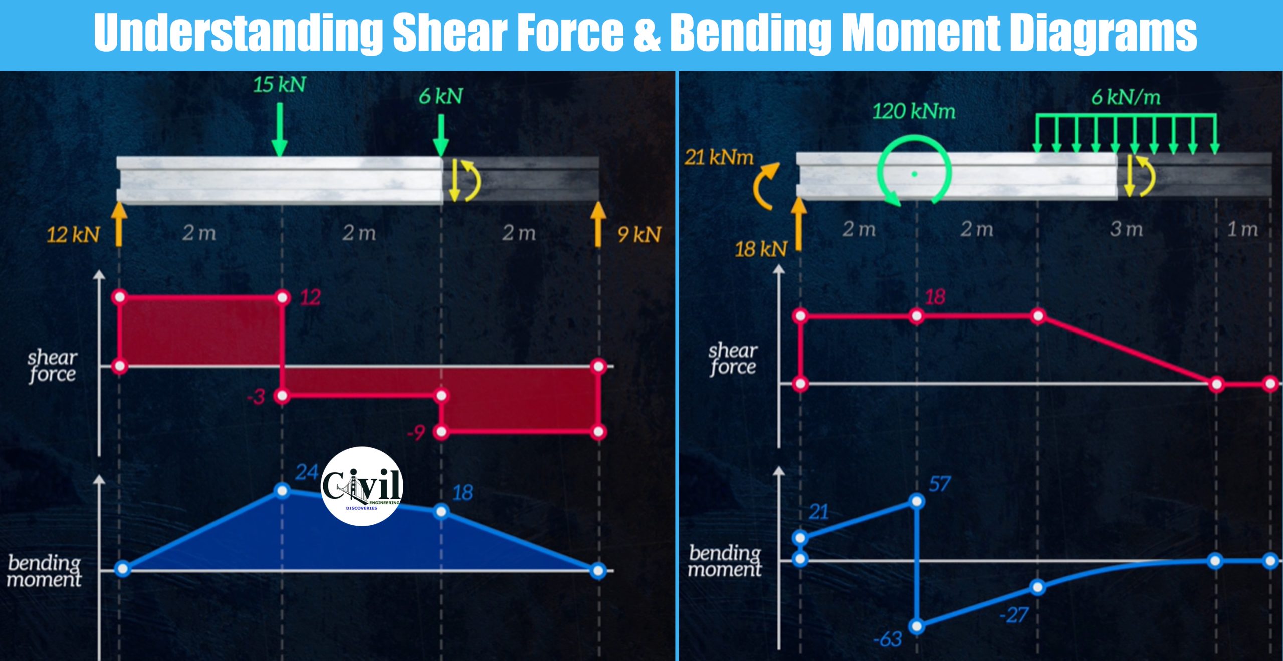
Web plots of v(x) and m(x) are known as shear and bending moment diagrams, and it is necessary to obtain them before the stresses can be determined. Relationship between load shear and moment. Shear force and bending moment diagrams are analytical tools used in conjunction with structural analysis to help perform structural design by determining the value of shear forces and bending moments at a. Establish the m and x axes and plot the values of the moment at the ends of the beam. To correctly determine the shear forces and bending moments along a beam we need to know all of the loads acting on it, which includes external loads and reaction loads at supports. Given the loading diagram, draw the shear and moment diagram. Shear/moment diagrams are graphical representations of the internal shear force and bending moment along the whole beam. Shear force and bending moment diagram example #5: Here's an example of a cut made just after the first support (which has an upward force. From left to right, make “cuts” before and after each reaction/load.
Understanding Shear Force And Bending Moment Diagrams Engineering
To calculate the bending moment of a beam, we must work in the same way we did for the. 2 relationships among load, shear, and moment diagrams. Shear/moment diagrams are graphical representations of the internal shear force and bending moment along the whole beam. Assume that the beam is cut at point c a distance of x from he left.

Learn How To Draw Shear Force And Bending Moment Diagrams Engineering
To correctly determine the shear forces and bending moments along a beam we need to know all of the loads acting on it, which includes external loads and reaction loads at supports. Web the graph of the above equation is as shown below. All afds, sfds, and bmds follow these basic rules. M x = moment about a section of.

Mechanics Map Shear and Moment Diagrams
Cut beam to reveal internal forces and moments* ; Barred x = location of centoid. But to draw a shear force and bending moment diagram, we need to know how these values change across the structure. Web steps to construct shear force and bending moment diagrams. Web shear and moment diagrams consider a simple beam shown of length l that.

Shear and moment diagrams geekloki
Shear force and bending moment diagram example #4: They allow us to see where the maximum loads occur so that we can optimize the design to prevent failures and reduce the overall weight and cost of the structure. We will refer to them as we go through the following main steps in each example: From left to right, make “cuts”.

Shear force and bending moment diagram practice problem 3 YouTube
Web shear and moment diagrams consider a simple beam shown of length l that carries a uniform load of w (n/m) throughout its length and is held in equilibrium by reactions r 1 and r 2. Determine the maximum shear and maximum moment using area method. Lined up below the shear diagram, draw a set of axes. To correctly determine.
Solved Draw the shear and moment diagrams for the beam using
2 relationships among load, shear, and moment diagrams. Web there is zero bending moment at a hinge. Web 4.0 building shear and moment diagrams. We will refer to them as we go through the following main steps in each example: Web once you have the reactions, draw your free body diagram and shear force diagram underneath the beam.

Drawing Shear and Moment Diagrams for Beam YouTube
To calculate the bending moment of a beam, we must work in the same way we did for the. By drawing the free body diagram you identify all of these loads and show then on a sketch. M x = moment about a section of distance x. Web step 1 | draw a free body diagram. 20 kn 40 kn/m.

Learn How To Draw Shear Force And Bending Moment Diagrams Engineering
Web egr2312 lab experiment n°8 shearing and bending moment diagrams 1. And the area and location of centroid are defined as follows. Utilize this on your exams in strengths of. Determine the maximum shear and maximum moment using area method. Web 1.2 alternative drawing convention.

How to draw shear and moment diagrams YouTube
Cut beam to reveal internal forces and moments* ; Web 1.2 alternative drawing convention. Shear force and bending moment diagram example #4: Here's an example of a cut made just after the first support (which has an upward force. 2 relationships among load, shear, and moment diagrams.

Solved Draw the shear and moment diagrams for the beam, and
Web egr2312 lab experiment n°8 shearing and bending moment diagrams 1. We go through breaking a beam into segments, and then we learn about the relatio. But to draw a shear force and bending moment diagram, we need to know how these values change across the structure. Here's an example of a cut made just after the first support (which.
Using The Machine In Figure 1, We Will Measure The Shear Force And Bending Moment Of A Beam After Subjecting It To Given Loads.
But to draw a shear force and bending moment diagram, we need to know how these values change across the structure. Also, draw shear and moment. We go through breaking a beam into segments, and then we learn about the relatio. You'll get a detailed solution from a subject matter expert that helps you learn core concepts.
Cut Beam To Reveal Internal Forces And Moments* ;
Web for example, if w(x) is uniform, v(x) will be linear. M x = moment about a section of distance x. Web 6.2 shear/moment diagrams 6.2.1 what are shear/moment diagrams? Calculate the reaction forces using equilibrium equations ( ∑ forces = 0 and ∑ moments = 0 );
Degree = Degree Power Of The Moment Diagram.
Determine new origin (x n) and use positive sign conventions to. A = 1 n + 1bh a = 1 n + 1 b h. Web 4.0 building shear and moment diagrams. Shear/moment diagrams are graphical representations of the internal shear force and bending moment along the whole beam.
Shear Force And Bending Moment Diagram Example #5:
They allow us to see where the maximum loads occur so that we can optimize the design to prevent failures and reduce the overall weight and cost of the structure. Shear force and bending moment diagrams are analytical tools used in conjunction with structural analysis to help perform structural design by determining the value of shear forces and bending moments at a. Draw a fbd of the structure. Web once you have the reactions, draw your free body diagram and shear force diagram underneath the beam.