Draw The Shear And Moment Diagrams For The Loaded Beam
Draw The Shear And Moment Diagrams For The Loaded Beam - Web beam guru.com is a online calculator that generates bending moment diagrams (bmd) and shear force diagrams (sfd), axial force diagrams (afd) for any statically determinate (most simply supported and cantilever beams) and statically indeterminate beams, frames and trusses. Web the first step in calculating these quantities and their spatial variation consists of constructing shear and bending moment diagrams, \(v(x)\) and \(m(x)\), which are the internal shearing forces and bending moments induced in. X 1 = 0.15m x 2 = 0.10m x 3 = 0.05m a = 0.105m step 1: But in order to find the shear and moment at every point in the object you will need a more powerful approach. Shear and moment diagrams and formulas are excerpted from the western woods use book, 4th edition, and are provided herein as a courtesy of. Internal forces in beams and frames, libretexts. Web the quickest way to tell a great cv writer from a great graduate engineer is to ask them to sketch a qualitative bending moment diagram for a given structure and load combination! Web shear force and bending moment diagrams are analytical tools used in conjunction with structural analysis to help perform structural design by determining the value of shear forces and bending moments at a given point of a structural element such as a beam. To create the shear force diagram, we will use the following process. So could please provide me a fbd of this beam.
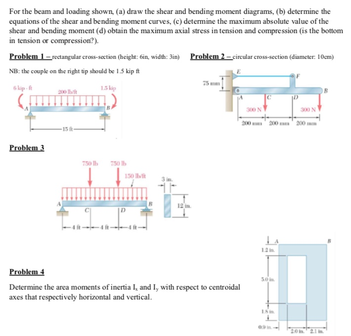
This is an example problem that will show you how to graphically draw a shear and moment diagram for a. But in order to find the shear and moment at every point in the object you will need a more powerful approach. This video explains how to draw shear force diagram and bending moment diagram with easy steps for a simply. This can be done by creating a shear and bending moment diagram. The goal of the beam analysis -determine the shear force v and Post any question and get expert help quickly. Mmax = 84 knm, σmax = 98.9 mpa. Shear and moment diagrams and formulas are excerpted from the western woods use book, 4th edition, and are provided herein as a courtesy of. 172k views 5 years ago civil engineering/structural engineering. Now taking moment about support a.
Web write shear and moment equations for the beams in the following problems. There are 2 steps to solve this one. Use the 'analysis' tab to view various criteria, such as: Web below is a simple example of what shear and moment diagrams look like, afterwards, the relation between the load on the beam and the diagrams will be discussed. Figures 1 through 32 provide a series of shear and moment diagrams with accompanying formulas for design of beams under various static loading conditions. The distributed load is the slope of the shear diagram and each point load represents a jump in the shear diagram. David roylance department of materials science and engineering massachusetts institute of technology cambridge, ma 02139 november 15, 2000. Find the ax, ay and by values i actually need a fbd diagram before the graphs. Also, draw shear and moment diagrams, specifying values at all change of loading positions and at. Adjust the tension springs if necessary.
Solved Draw the shear and moment diagrams for the loaded
Web the first step in calculating these quantities and their spatial variation consists of constructing shear and bending moment diagrams, \(v(x)\) and \(m(x)\), which are the internal shearing forces and bending moments induced in. We go through breaking a beam into segments, and then we learn about the relatio. R= i draw the shear and moment diagrams for the loaded.

Draw The Shear Diagram For The Beam
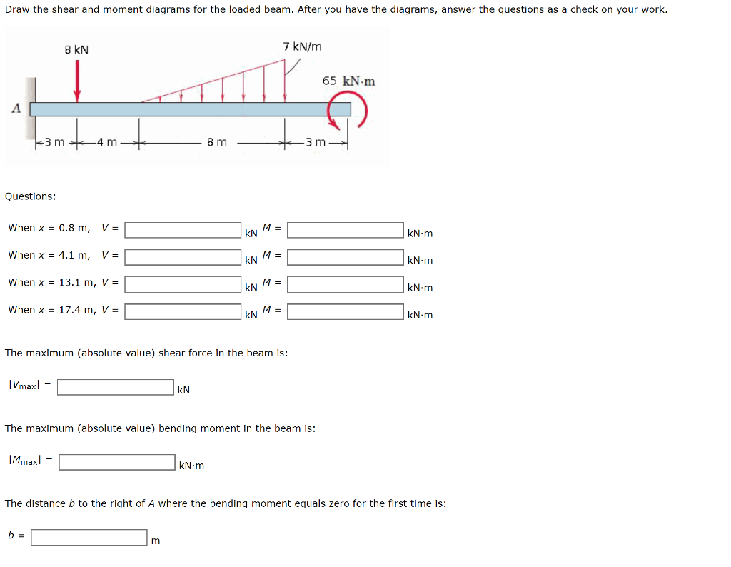
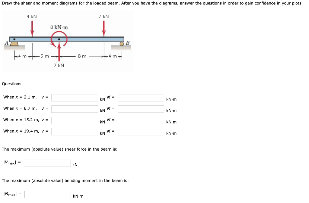
State the value of the bending moment at midbeam. X 1 = 0.15m x 2 = 0.10m x 3 = 0.05m a = 0.105m step 1: When x = 1.3 m, v = kn m= kn.m when x = 6.9 m, v = m = kn kn.m when x = 16.6 m, v = kn m= kn.m when x =..
For The Beam And Loading Shown Draw Shear Bending Moment Diagrams
Web write shear and moment equations for the beams in the following problems. 172k views 5 years ago civil engineering/structural engineering. State the value of the bending moment at midbeam. Web learn to draw shear force and moment diagrams using 2 methods, step by step. The goal of the beam analysis -determine the shear force v and
Solved 2 Draw The Shear And Moment Diagrams Of The Beam Images
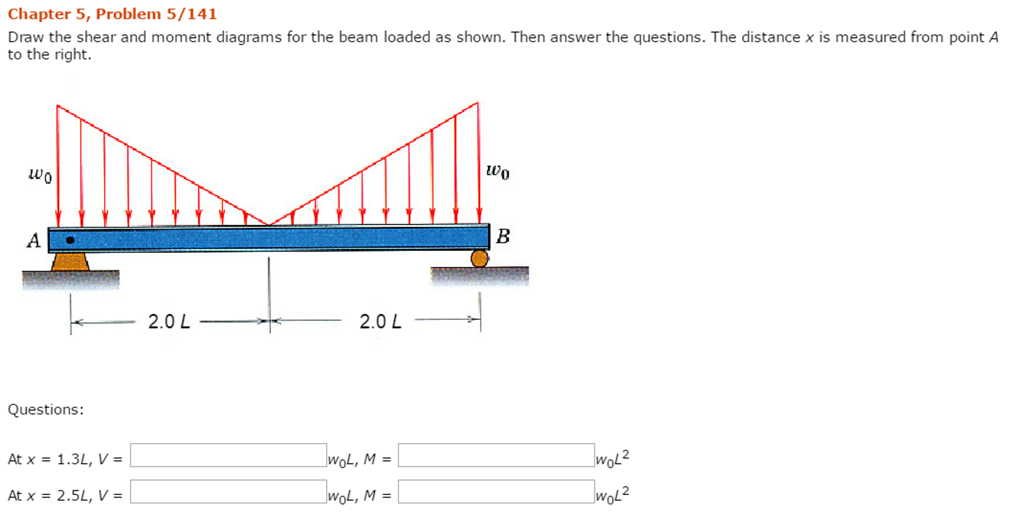
Adjust the tension springs if necessary. Web there are 4 steps to solve this one. In each problem, let x be the distance measured from left end of the beam. After you have the diagrams, answer the questions as a check on your work. Web draw the shear and moment diagrams for the beam.
draw the shear and moment diagrams for the beam chegg
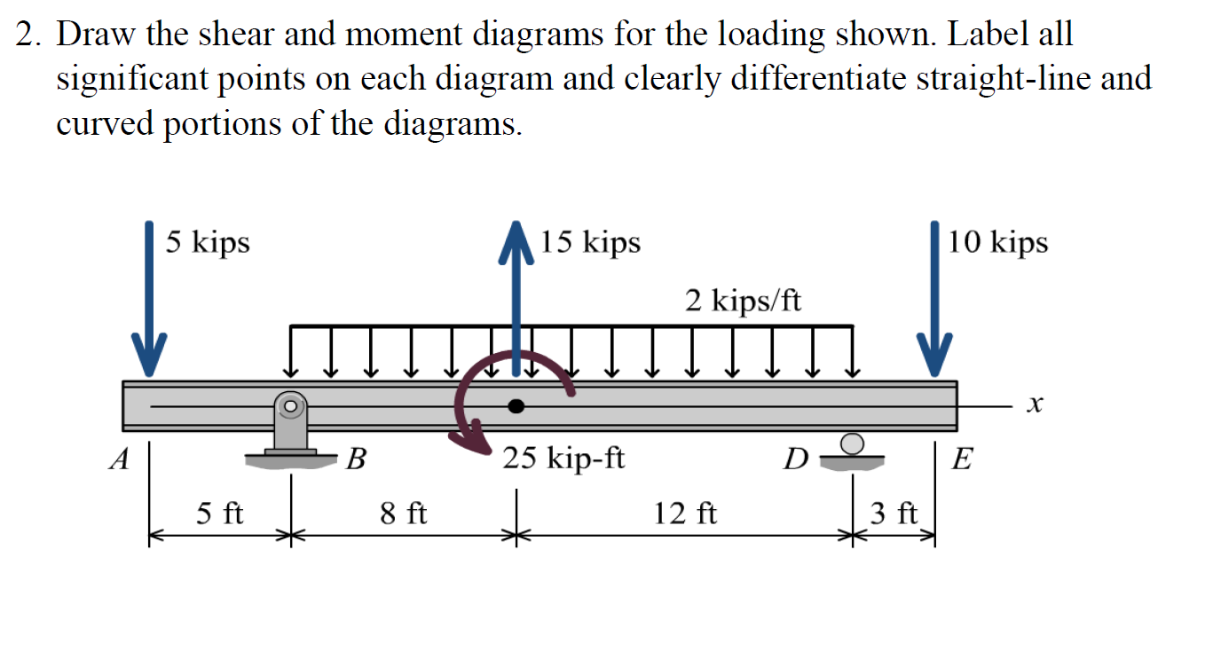
This is an example problem that will show you how to graphically draw a shear and moment diagram for a. View the full answer step 2. I do not know how to implement the force of 15 kn Shear and moment diagramsthe beam is subjected to the uniform distributed load shown. Web shear force and bending moment diagrams are analytical.

Shear Force and Bending Moment diagram of Beam with Triangular Load
Web below is a simple example of what shear and moment diagrams look like, afterwards, the relation between the load on the beam and the diagrams will be discussed. ∑ m a = 0. Draw the shear force and bending moment diagrams for the loaded beam shown below. Now taking moment about support a. View the full answer step 2.

Solved Draw the shear and moment diagrams for the beam, and
Without there being any load applied to the beam, check that the beam is in its equilibrium position. Also, draw shear and moment diagrams, specifying values at all change of loading positions and at. After you have the diagrams, answer the questions as a check on your work. This video explains how to draw shear force diagram and bending moment.
Solved Draw the shear and moment diagrams for the loaded
Not the question you’re looking for? State the value of the bending moment at midbeam. This can be done by creating a shear and bending moment diagram. Now taking moment about support a. Web there are 4 steps to solve this one.
Solved Draw the shear and moment diagrams for the beam
Internal forces in beams and frames, libretexts. So could please provide me a fbd of this beam. R a + r b = 6 × 6 + 31 + 1 2 × 9 × 13 = 125.5 k n. Leave all distributed forces as distributed forces and do not replace them with the equivalent point load. The goal of the.

Learn How To Draw Shear Force And Bending Moment Diagrams Engineering
Internal forces in beams and frames, libretexts. 5/106 draw the shear and moment diagrams for the loaded cantilever beam. ∑ m a = 0. Draw out a free body diagram of the body horizontally. To create the shear force diagram, we will use the following process.
This Can Be Done By Creating A Shear And Bending Moment Diagram.
Internal forces in beams and frames, libretexts. Find the ax, ay and by values i actually need a fbd diagram before the graphs. We go through breaking a beam into segments, and then we learn about the relatio. State the value of the bending moment at midbeam.
After You Have The Diagrams, Answer The Questions As A Check On Your Work.
So in this post we’ll give you a thorough introduction to shear forces, bending moments and how to draw shear and moment diagrams. Shear and moment diagrams and formulas are excerpted from the western woods use book, 4th edition, and are provided herein as a courtesy of. Use the 'analysis' tab to view various criteria, such as: Mmax = 84 knm, σmax = 98.9 mpa.
Web Write Shear And Moment Equations For The Beams In The Following Problems.
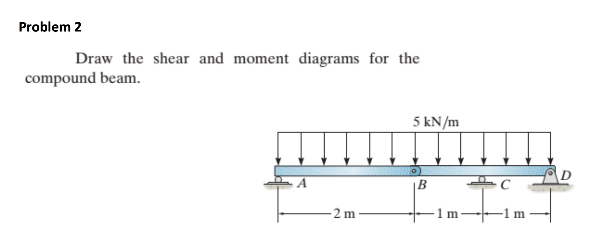
The distributed load is the slope of the shear diagram and each point load represents a jump in the shear diagram. Draw the shear force and bending moment diagrams for the loaded beam shown below. Web draw the shear and moment diagrams for the loaded beam. The goal of the beam analysis -determine the shear force v and
Not The Question You’re Looking For?
Shear and bending moment diagrams. Draw the shear and moment diagramsfor the beam.take :a=,2,mb=,1.5,mc=,2,knmsolution :equation of equilibrium: Since δx δ x is infinitely narrow, we can assume that the distributed load over this small distance is constant and equal to the value at x, x, and call it w. Solve for all external forces acting on the body.