Draw The Shear And Moment Diagrams For The Simplysupported Beam
Draw The Shear And Moment Diagrams For The Simplysupported Beam - Web how to draw sfd and bmd for a simply supported beam? (a) is loaded by the clockwise couple c 0 at b. Mmax = 84 knm, σmax = 98.9 mpa. This is an example problem that will show you how to graphically draw a shear and moment diagram for a beam. [latex]\delta m=\int v (x)dx [/latex] (equation 6.2) equation 6.2 states that the change in moment equals the area under the shear diagram. We go through breaking a beam into segments, and then we learn about the relatio. Web how to draw shear and moment diagram for a simply supported beam? Draw shear force and bending moment diagrams [sfd and bmd] for a simply supported beam subjected to loading as shown in the fig. Please, enable ads on this site. Also locate and determine absolute maximupobkending moment.
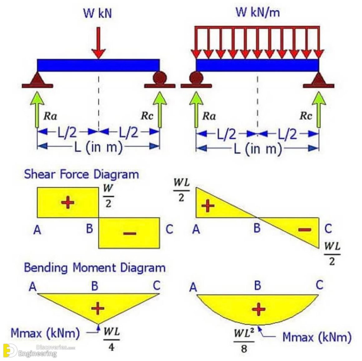
We go through breaking a beam into segments, and then we learn about the relatio. And (2) draw the shear force and bending moment diagrams. To find these weak points, we need to check the internal loading at every point along the beam’s full length. Solution part 1 due to the. The solution for \(v(x)\) and \(m(x)\) takes the following steps: In this video, shear stress and bending. M ( x) = 1 / 2 ⋅ q ⋅ x ⋅ ( l − x) max bending moment. Simply supported beam with point load example. Draw shear forces and bending moment diagrams for the beams given below: 455 views 1 year ago pakistan.
Find the shear forces and bending moment at the critical points. [latex]\delta m=\int v (x)dx [/latex] (equation 6.2) equation 6.2 states that the change in moment equals the area under the shear diagram. Assume that the flexural rigidity is a multiple of ei and differs for each member as shown in the figure. The support reactions a and c have been computed, and their values are shown in fig. Shear force and bending moment values are calculated at supports and at points where load varies. Fig:6 formulas for finding moments and reactions at different sections of a simply supported beam having udl at right support. Solution part 1 due to the. M m a x = 1 / 8 ⋅ q ⋅ l 2. This video explains how to draw shear force diagram and bending moment. M ( x) = 1 / 2 ⋅ q ⋅ x ⋅ ( l − x) max bending moment.
SHEAR FORCE AND BENDING MOMENT DIAGRAM FOR SIMPLY SUPPORTED BEAM WITH
In this video, shear stress and bending. Web how to draw sfd and bmd for a simply supported beam? 7.1 setup and shear force diagram The solution for \(v(x)\) and \(m(x)\) takes the following steps: Web our calculator generates the reactions, shear force diagrams (sfd), bending moment diagrams (bmd), deflection, and stress of a cantilever beam or simply supported beam.

Draw shear force and bending moment diagrams for a simply supported
And (2) draw the shear force and bending moment diagrams. 92k views 3 years ago statics. Web shear force and bending moment diagrams are analytical tools used in conjunction with structural analysis to help perform structural design by determining the value of shear forces and bending moments at a given point of a structural element such as a beam. Web.

Shear Force & Bending Moment Diagram for Uniformly Distributed Load on
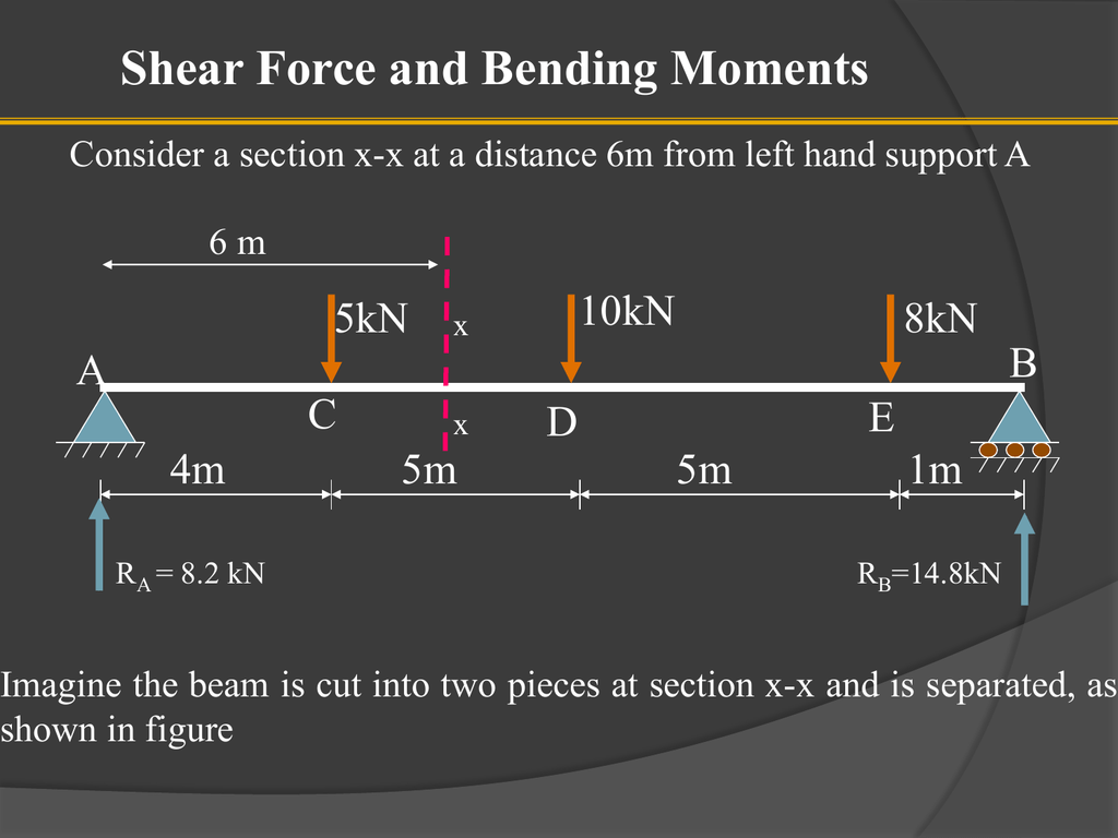
In this video i find the end. The support reactions a and c have been computed, and their values are shown in fig. Internal forces in beams and frames, libretexts. Web how to draw sfd and bmd for a simply supported beam? Equation 6.1 suggests the following expression:

Shear force and bending moment diagrams for a simply supported beam
M ( x) = 1 / 2 ⋅ q ⋅ x ⋅ ( l − x) max bending moment. 7.1 setup and shear force diagram Web how to draw shear and moment diagram for a simply supported beam? Web learn to draw shear force and moment diagrams using 2 methods, step by step. Also locate and determine absolute maximupobkending moment.

Learn How To Draw Shear Force And Bending Moment Diagrams Engineering
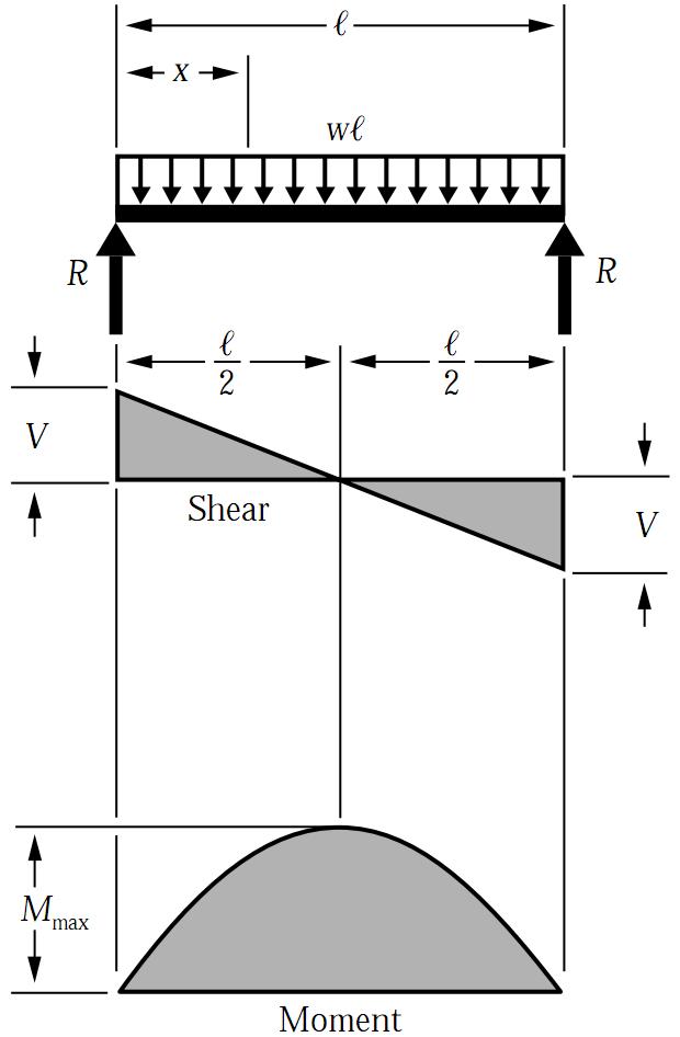
(a) is loaded by the clockwise couple c 0 at b. In this video i find the end. Web below is a simple example of what shear and moment diagrams look like, afterwards, the relation between the load on the beam and the diagrams will be discussed. 455 views 1 year ago pakistan. Draw the shear force, axial force and.
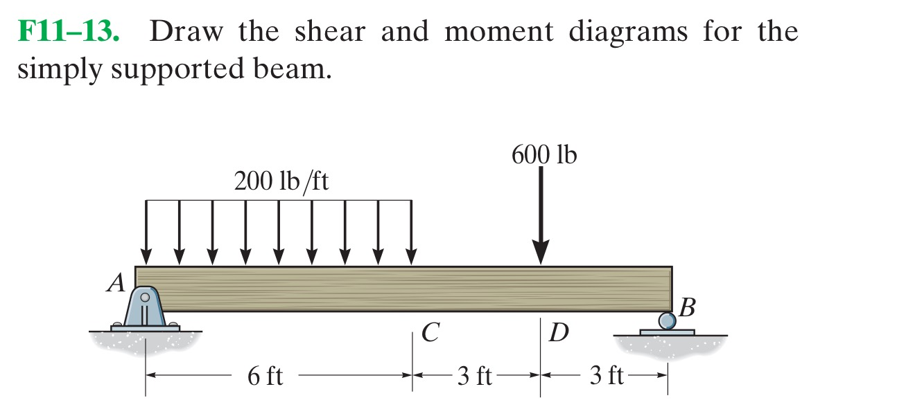
Solved Draw the shear and moment diagrams for the simply
As we used fe programs to calculate the bending moments, shear forces and deflections of structures in last tutorials, we are going a step back now to the very basics of structural engineering and do hand calculations. V a = − v b = 1 / 2 ⋅ q ⋅ l. Draw the shear force, axial force and bending moment.
Draw The Shear And Moment Diagrams For Simply Support vrogue.co
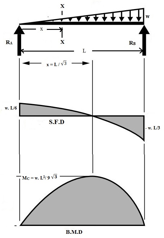
Web fig:5 shear force and bending moment diagram for simply supported uniformly distributed load at left support. As we used fe programs to calculate the bending moments, shear forces and deflections of structures in last tutorials, we are going a step back now to the very basics of structural engineering and do hand calculations. In this video we are going.
How To Draw Shear Force And Bending Moment Diagram For Simply Supported
Draw shear forces and bending moment diagrams for the beams given below: Web how to draw sfd and bmd for a simply supported beam? As we used fe programs to calculate the bending moments, shear forces and deflections of structures in last tutorials, we are going a step back now to the very basics of structural engineering and do hand.
Simply Supported UDL Beam Formulas Bending Moment Equations
172k views 5 years ago civil engineering/structural engineering. Web when designing a beam it is important to locate the points of maximum shear and maximum moment and their magnitudes because that’s where the beam is most likely to fail. Web how to draw sfd and bmd for a simply supported beam? Web the equation also suggests that the slope of.
Shear and Moment Diagram Simply Supported Beam (Point Load) YouTube
Web fig:5 shear force and bending moment diagram for simply supported uniformly distributed load at left support. Web simply supported beam: 92k views 3 years ago statics. Neglect the mass of the beam in each problem. By laurin ernst updated december 30, 2022.
Also Locate And Determine Absolute Maximupobkending Moment.
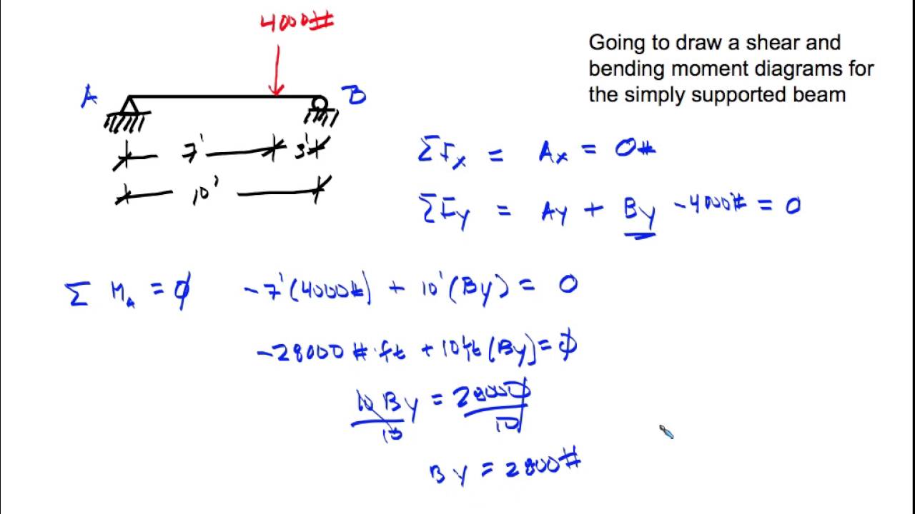
Web ay this will allow you to find external ex bx' bx' bx bx by' by' by by cy ey reaction forces at the supports and internal reaction forces at the hinge. Web when designing a beam it is important to locate the points of maximum shear and maximum moment and their magnitudes because that’s where the beam is most likely to fail. Web the equation also suggests that the slope of the moment diagram at a particular point is equal to the shear force at that same point. Solution part 1 due to the.
Web Simply Supported Beam:
By laurin ernst updated december 30, 2022. Moment and shear hand calculation. Web shear force and bending moment diagram of simply supported beam can be drawn by first calculating value of shear force and bending moment. Assume that the flexural rigidity is a multiple of ei and differs for each member as shown in the figure.
As We Used Fe Programs To Calculate The Bending Moments, Shear Forces And Deflections Of Structures In Last Tutorials, We Are Going A Step Back Now To The Very Basics Of Structural Engineering And Do Hand Calculations.
V a = − v b = 1 / 2 ⋅ q ⋅ l. Shear and moment diagrams and formulas are excerpted from the western woods use book, 4th edition, and are provided herein as a courtesy of western wood products association. Web figures 1 through 32 provide a series of shear and moment diagrams with accompanying formulas for design of beams under various static loading conditions. M ( x) = 1 / 2 ⋅ q ⋅ x ⋅ ( l − x) max bending moment.
7.1 Setup And Shear Force Diagram
In this video we are going to learn about how to solve problems on shear. Neglect the mass of the beam in each problem. This is an example problem that will show you how to graphically draw a shear and moment diagram for a beam. The simply supported beam is one of the most simple structures.