Drawing Mechanical Objects
Drawing Mechanical Objects - Mechanical drawing is used to convey precise information from one person to another so that a pattern maker will have a true drawing of an object, giving correct dimensions and instructions before he can make a pattern, from this, the foundry man can make a rough casting. Web isometric drawing the representation of the object in figure 2 is called an isometric drawing. When creating large or complex technical drawings for manufacturing, it is good practice to include coordinate divisions along the border as reference points when discussing a dimension or feature. Web engineering drawings serve several important purposes: Web ask the assistant. See more ideas about object drawing, drawings, drawing inspiration. Area where the job specifications are listed. You can even flip between scales on the fly. To provide a permanent record of the design. Imagine that you have an object suspended by transparent threads inside a glass box, as in figure 3.
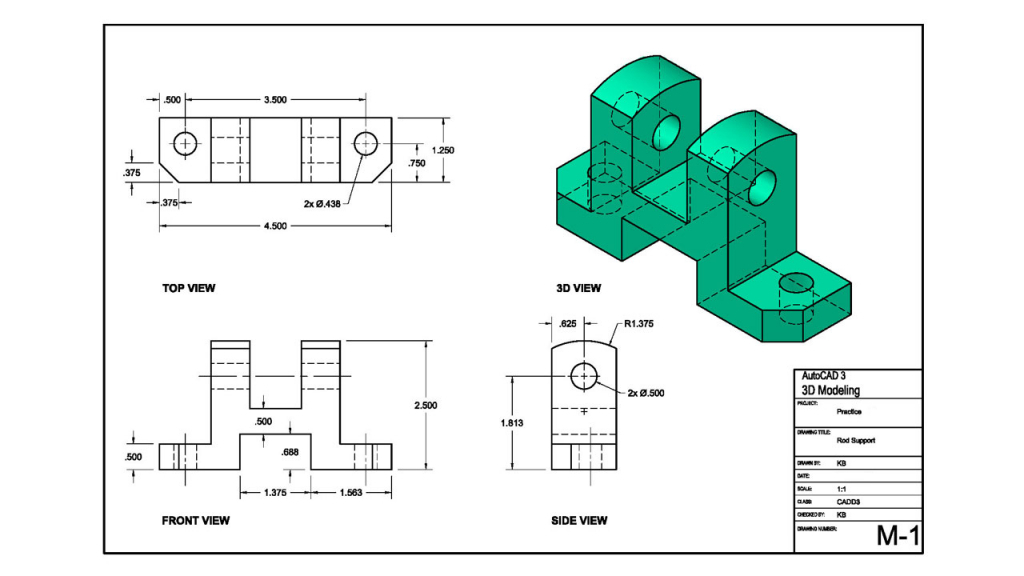
Web orthographic or multiview drawing. 1.dimensioning should be done in a logical sequence. Add coordinates and a notes list. Unfold the box (figure 4) and you have the three views. Web we are currently inviting engineers and designers to test early versions of leo ideation. Engineering drawings provide all the details needed to manufacture the product to the designer's specifications. 2.use the same units of measure, and decimal points, throughout the drawing. Bill of materials or material list. To communicate design specifications between engineers, manufacturers, and customers. The machinist must have a drawing.
Web isometric drawing the representation of the object in figure 2 is called an isometric drawing. Web we are currently inviting engineers and designers to test early versions of leo ideation. Area where the job specifications are listed. In that case, the graphic language of the drawing would help manufacturing engineers align their operations according to the drawing drafted by the cad engineer or a draftsman. You can even flip between scales on the fly. 1.dimensioning should be done in a logical sequence. In an isometric drawing, the object’s vertical lines are drawn vertically, and the horizontal lines in the width and depth planes are shown at 30 degrees to the horizontal. These are various types of lines commonly used in technical drawings, engineering, and architectural drafting: See more ideas about a level art, drawings, ap art. When creating large or complex technical drawings for manufacturing, it is good practice to include coordinate divisions along the border as reference points when discussing a dimension or feature.
Starting to Draw Mechanical objects
Web mechanical 101 is designed to teach students how to draw mechanical objects in 2d and how to navigate/manipulate autocad software. The most important ones include solid lines (representing visible edges or boundaries of objects), dashed lines (indicating hidden or invisible parts behind other elements), dotted lines (used for centerlines or symmetry), and thin lines (for dimensions, extension, and. This.

Mechanical Drawing Exhibition at Kirkaldy Testing Museum in London
Walsh (cw)'s board mechanical object drawing inspiration on pinterest. You can even flip between scales on the fly. Basic layout of a drawing. Aligned, the dimensions are written parallel to their dimension line. 1.dimensioning should be done in a logical sequence.

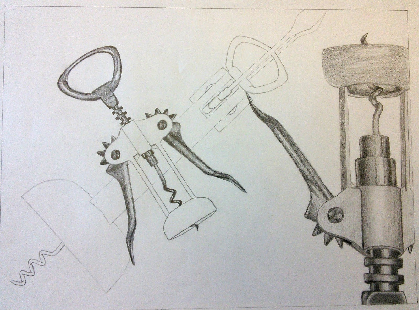
Ꮰσ'ʂ Ꮆαɽαɠҽ Mechanical art, School art projects, Observational drawing
2.use the same units of measure, and decimal points, throughout the drawing. Web orthographic or multiview drawing. Web smartdraw provides thousands of mechanical drawing symbols that you can drag and drop, then add lines and text. The most important ones include solid lines (representing visible edges or boundaries of objects), dashed lines (indicating hidden or invisible parts behind other elements),.

Mechanical Pencil Drawing Techniques How To Draw With A Mechanical
Leo is the world's first engineering design copilot, empowering engineers to turn ideas into products in seconds. Mechanical drawing is used to convey precise information from one person to another so that a pattern maker will have a true drawing of an object, giving correct dimensions and instructions before he can make a pattern, from this, the foundry man can.
Mechanical Drawing at GetDrawings Free download
Break lines are used to represent a long object or feature that is too large to be shown in its entirety on a drawing. This course will also cover simple to complex features within autocad while teaching you drafting sops used throughout the drafting industry. Walsh (cw)'s board mechanical object drawing inspiration on pinterest. Add coordinates and a notes list..

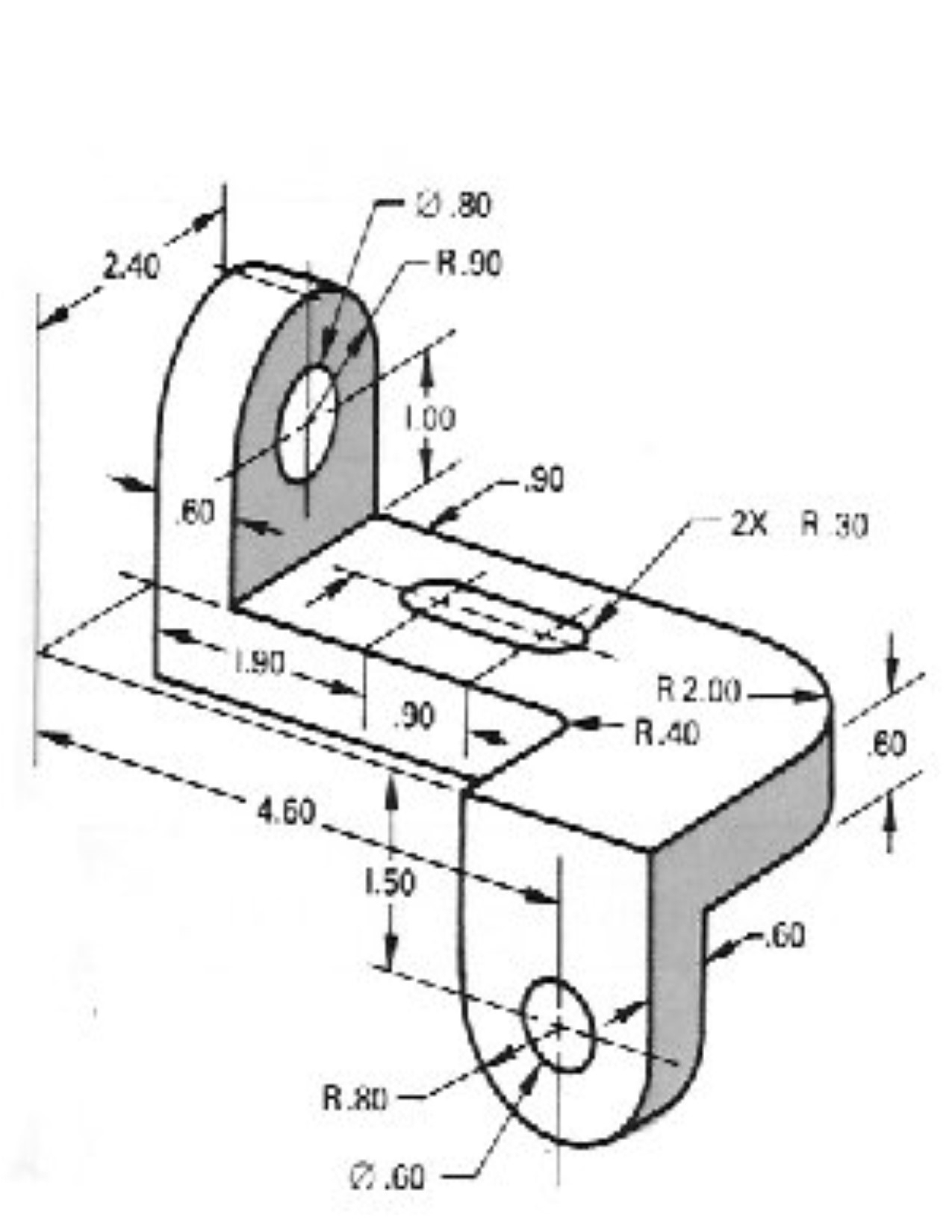
Mechanical Drawing With Dimension
When creating large or complex technical drawings for manufacturing, it is good practice to include coordinate divisions along the border as reference points when discussing a dimension or feature. Web mechanical 101 is designed to teach students how to draw mechanical objects in 2d and how to navigate/manipulate autocad software. Then draw the object on each of three faces as.
The best free Mechanical drawing images. Download from 621 free
Web orthographic or multiview drawing. Retain a space for a notes list in the top left corner of the page to display materials and coding. We will go step by step, explaining every element of the section view. 1.dimensioning should be done in a logical sequence. Web smartdraw provides thousands of mechanical drawing symbols that you can drag and drop,.

262 Best Mechanical Drawings Blueprints Cad Drawings vrogue.co
1.dimensioning should be done in a logical sequence. The most important ones include solid lines (representing visible edges or boundaries of objects), dashed lines (indicating hidden or invisible parts behind other elements), dotted lines (used for centerlines or symmetry), and thin lines (for dimensions, extension, and. Two methods of dimensioning are in common use. Bill of materials or material list..
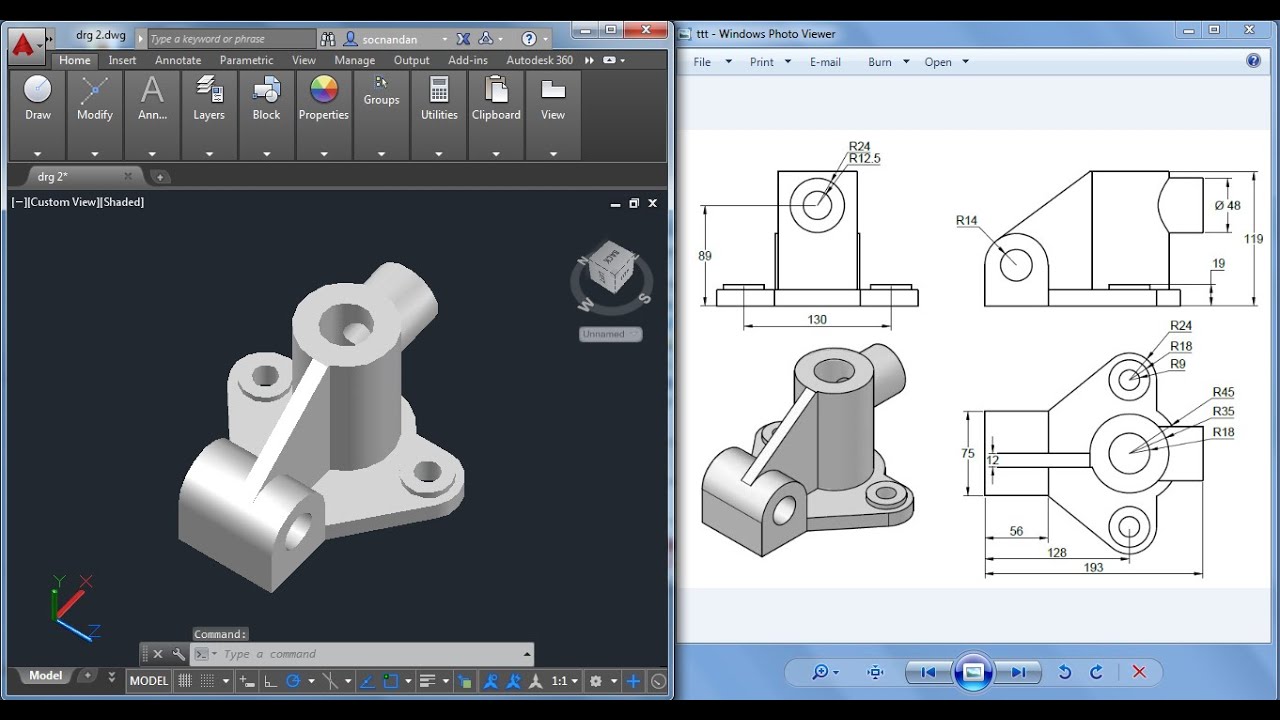
Autocad Mechanical Drawings Samples at Explore
Unfold the box (figure 4) and you have the three views. Web ask the assistant. Web elements of the section views. The drawing serves as the. In an isometric drawing, the object’s vertical lines are drawn vertically, and the horizontal lines in the width and depth planes are shown at 30 degrees to the horizontal.

Understanding Mechanical Drawings Mechanical Drafting Course
You can even flip between scales on the fly. The layout of most drawings is similar in that the drawing format has some standard features or components. Web ask the assistant. In that case, the graphic language of the drawing would help manufacturing engineers align their operations according to the drawing drafted by the cad engineer or a draftsman. A.
Web Ask The Assistant.
When creating large or complex technical drawings for manufacturing, it is good practice to include coordinate divisions along the border as reference points when discussing a dimension or feature. Mechanical drawing is used to convey precise information from one person to another so that a pattern maker will have a true drawing of an object, giving correct dimensions and instructions before he can make a pattern, from this, the foundry man can make a rough casting. Web mechanical 101 is designed to teach students how to draw mechanical objects in 2d and how to navigate/manipulate autocad software. This course will also cover simple to complex features within autocad while teaching you drafting sops used throughout the drafting industry.
To Communicate Design Specifications Between Engineers, Manufacturers, And Customers.
Break lines are used to represent a long object or feature that is too large to be shown in its entirety on a drawing. The main elements of the section view are: 1.dimensioning should be done in a logical sequence. The most important ones include solid lines (representing visible edges or boundaries of objects), dashed lines (indicating hidden or invisible parts behind other elements), dotted lines (used for centerlines or symmetry), and thin lines (for dimensions, extension, and.
Bill Of Materials Or Material List.
Add coordinates and a notes list. Smartdraw works in both us/imperial and metric standards of measure and also allows you to customize the scale of your mechanical drawing. Unfold the box (figure 4) and you have the three views. The drawing serves as the.
Retain A Space For A Notes List In The Top Left Corner Of The Page To Display Materials And Coding.
Web drawing a mechanical engineering object typically involves creating detailed and accurate technical drawings using standard conventions. Aligned, the dimensions are written parallel to their dimension line. To provide a permanent record of the design. Web we are currently inviting engineers and designers to test early versions of leo ideation.