Drawing Projection
Drawing Projection - Orthographic views can show us an object viewed from each direction. Web first angle and third angle projection are the types of orthographic projection systems to draw engineering drawings. It could be an image of any object like a point, line, plane, solid, machine component, or building. The orthographic projection method is employed in making engineering drawings. Web when the large end of the cone in the section view is closest to the top view, this is known as first angle projection. There is a strong chance you will have seen symbols like this on an engineering drawing: Web for engineering applications, the orthographic projection is the tool of choice in most cases. Web understanding the difference between first angle and third angle projection can help prevent costly mistakes and is crucial to being a good engineer. How the views are laid out on a drawing depends on whether 3 rd angle or 1 st angle projection is being used. Mathematically, an orthographic projection is created by defining a flat projection plane, and then projecting the features of the 3d object onto the plane along lines (or projectors) which are perpendicular to the.
The two main types of views (or “projections”) used in drawings are: Web an image that is represented on a surface or plane is referred to as a projection. They are used by architecture students and professionals alike to communicate designs and ideas to tutors, peers, clients, and contractors. Web for engineering applications, the orthographic projection is the tool of choice in most cases. Web understanding the difference between first angle and third angle projection can help prevent costly mistakes and is crucial to being a good engineer. There are three types of pictorial views: Web when the large end of the cone in the section view is closest to the top view, this is known as first angle projection. Web drawing more than one face of an object by rotating the object relative to your line of sight helps in understanding the 3d form. The orthographic projection method is employed in making engineering drawings. Orthographic views can show us an object viewed from each direction.
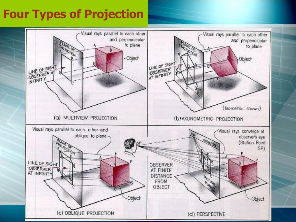
They are used by architecture students and professionals alike to communicate designs and ideas to tutors, peers, clients, and contractors. Web by gd&t basics on march 30, 2021. For example, they are usually on the border of a drawing: The orthographic projection method is employed in making engineering drawings. Web since the visual rays, called projectors, are perpendicular, i.e., orthogonal to the plane of projection the view is called orthographic view and the projection method is called orthographic projection. Mathematically, an orthographic projection is created by defining a flat projection plane, and then projecting the features of the 3d object onto the plane along lines (or projectors) which are perpendicular to the. Web understanding the difference between first angle and third angle projection can help prevent costly mistakes and is crucial to being a good engineer. Web for engineering applications, the orthographic projection is the tool of choice in most cases. There is a strong chance you will have seen symbols like this on an engineering drawing: Web architecture drawing projections are a means of representing three dimensional buildings, structures, detailed components, and other architecture related information onto two dimensional surfaces.
Drafting Teacher blog Orthographic Projection
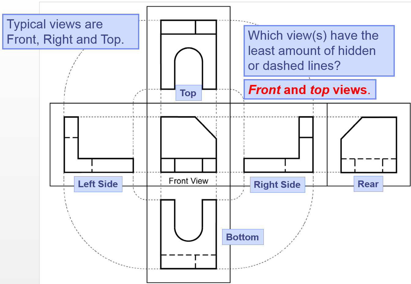
Web by gd&t basics on march 30, 2021. Web types of views used in drawings. The two main types of views (or “projections”) used in drawings are: How the views are laid out on a drawing depends on whether 3 rd angle or 1 st angle projection is being used. There are three types of pictorial views:
Orthographic Projection Drawing Orthographic Projection Orthographic
Web types of views used in drawings. There are three types of pictorial views: Web architecture drawing projections are a means of representing three dimensional buildings, structures, detailed components, and other architecture related information onto two dimensional surfaces. Web since the visual rays, called projectors, are perpendicular, i.e., orthogonal to the plane of projection the view is called orthographic view.
Orthographic Projection, Drawing A Comprehensive Guide.
Web since the visual rays, called projectors, are perpendicular, i.e., orthogonal to the plane of projection the view is called orthographic view and the projection method is called orthographic projection. The orthographic projection method is employed in making engineering drawings. They are used by architecture students and professionals alike to communicate designs and ideas to tutors, peers, clients, and contractors..
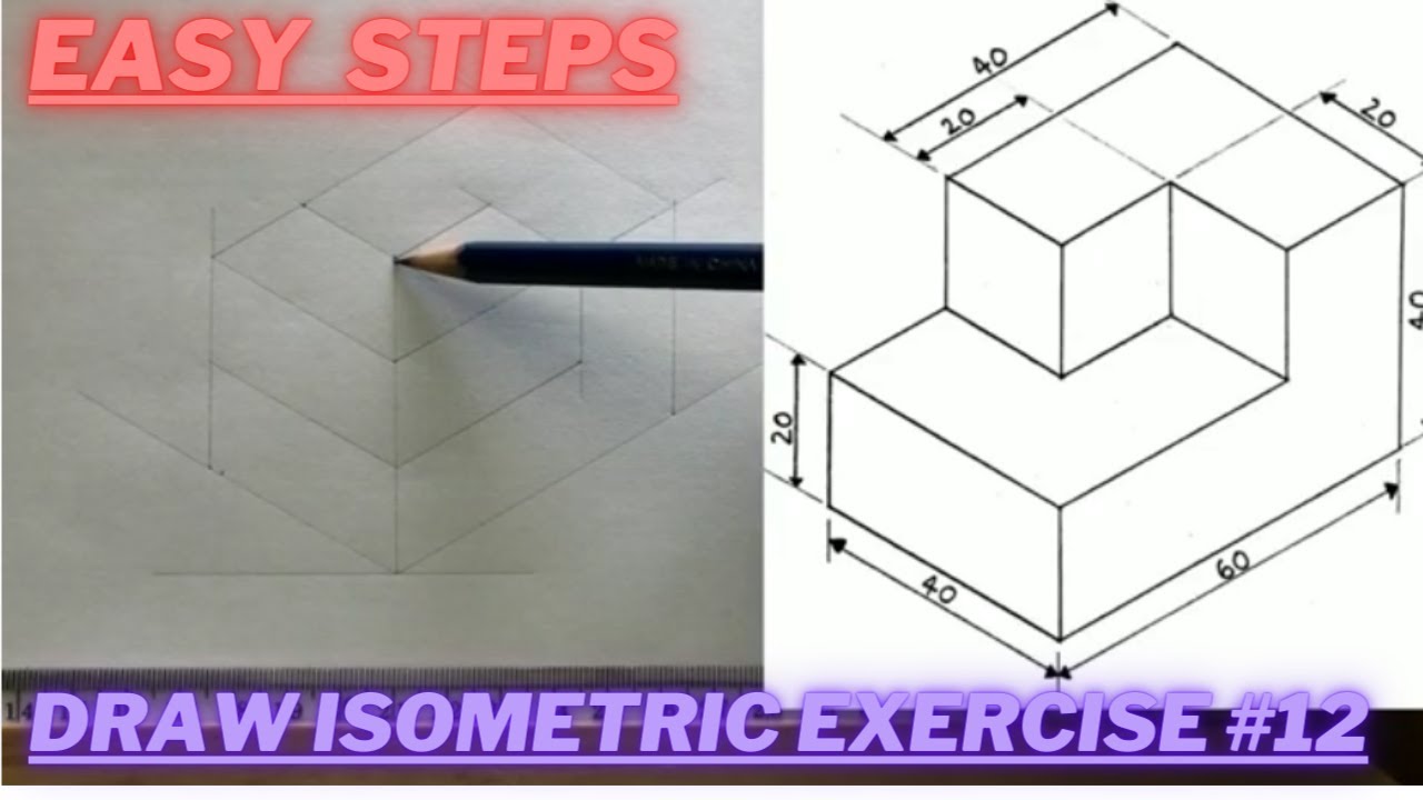
How to draw ISOMETRIC PROJECTIONS Technical Drawing Exercise 12
The two main types of views (or “projections”) used in drawings are: Web for engineering applications, the orthographic projection is the tool of choice in most cases. The orthographic projection method is employed in making engineering drawings. How the views are laid out on a drawing depends on whether 3 rd angle or 1 st angle projection is being used..
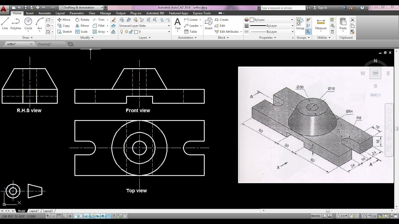
How to draw orthographic projection in autocad ? YouTube
There are three types of pictorial views: Traditionally, the first angle projection symbol is drawn with the top view on the left and the side view on the right. Web for engineering applications, the orthographic projection is the tool of choice in most cases. Web architecture drawing projections are a means of representing three dimensional buildings, structures, detailed components, and.

Basic Engineering Drawing Projection Knowledge Zone, The Online Support
The orthographic projection method is employed in making engineering drawings. Mathematically, an orthographic projection is created by defining a flat projection plane, and then projecting the features of the 3d object onto the plane along lines (or projectors) which are perpendicular to the. The two main types of views (or “projections”) used in drawings are: How the views are laid.
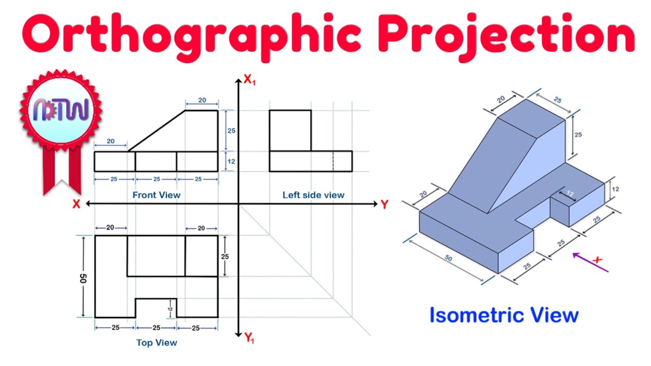
Orthographic Projection from isometric view in Engineering drawing
Mathematically, an orthographic projection is created by defining a flat projection plane, and then projecting the features of the 3d object onto the plane along lines (or projectors) which are perpendicular to the. It could be an image of any object like a point, line, plane, solid, machine component, or building. Web when the large end of the cone in.

ORTHOGRAPHIC PROJECTION IN ENGINEERING DRAWING FUNDAMENTAL YouTube
It could be an image of any object like a point, line, plane, solid, machine component, or building. Traditionally, the first angle projection symbol is drawn with the top view on the left and the side view on the right. Web an image that is represented on a surface or plane is referred to as a projection. Web when the.
PPT Orthographic Drawing PowerPoint Presentation, free download ID
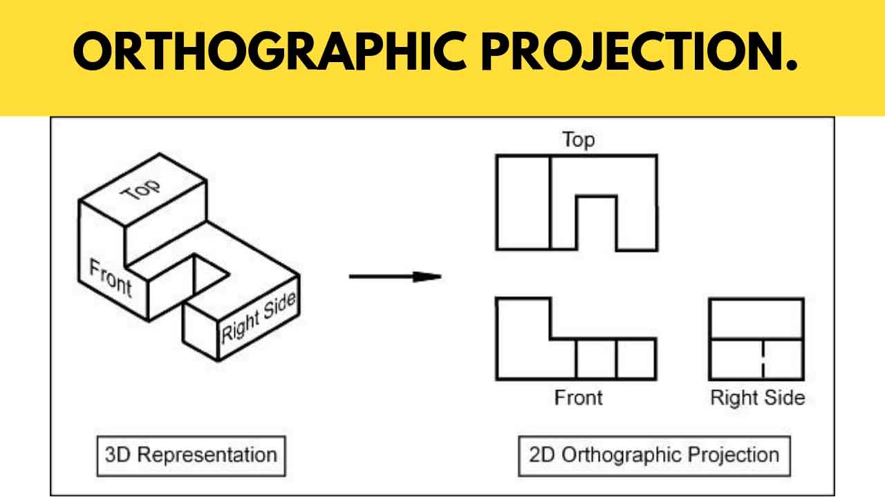
Orthographic views allow us to represent a 3d object in 2d on a drawing. The orthographic projection method is employed in making engineering drawings. Web drawing more than one face of an object by rotating the object relative to your line of sight helps in understanding the 3d form. Web understanding the difference between first angle and third angle projection.

ORTHOGRAPHIC PROJECTION IN ENGINEERING DRAWING YouTube
The two main types of views (or “projections”) used in drawings are: Web types of views used in drawings. How the views are laid out on a drawing depends on whether 3 rd angle or 1 st angle projection is being used. Web understanding the difference between first angle and third angle projection can help prevent costly mistakes and is.
Web For Engineering Applications, The Orthographic Projection Is The Tool Of Choice In Most Cases.
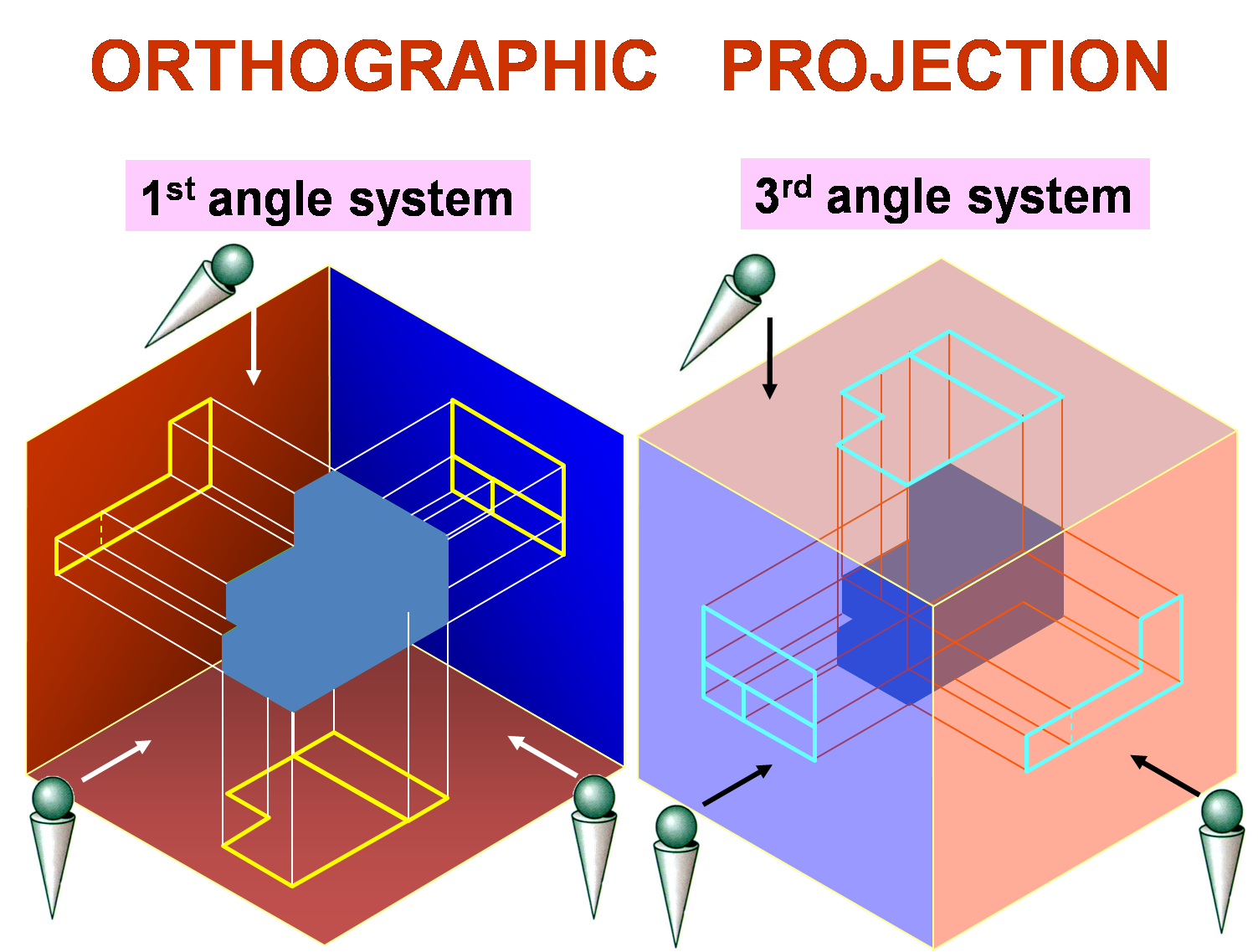
How the views are laid out on a drawing depends on whether 3 rd angle or 1 st angle projection is being used. Traditionally, the first angle projection symbol is drawn with the top view on the left and the side view on the right. It could be an image of any object like a point, line, plane, solid, machine component, or building. Mathematically, an orthographic projection is created by defining a flat projection plane, and then projecting the features of the 3d object onto the plane along lines (or projectors) which are perpendicular to the.
The 1St Angle Projection System Is Popular In European Countries, Whereas 3Rd Angle Projection Is Popular In North America And Asian Countries.
Orthographic views allow us to represent a 3d object in 2d on a drawing. Web drawing more than one face of an object by rotating the object relative to your line of sight helps in understanding the 3d form. The two main types of views (or “projections”) used in drawings are: Technical drawings can create projections based on where the person is looking as well as the direction of where the projector is showing.
Web Understanding The Difference Between First Angle And Third Angle Projection Can Help Prevent Costly Mistakes And Is Crucial To Being A Good Engineer.
Web types of views used in drawings. There is a strong chance you will have seen symbols like this on an engineering drawing: Web by gd&t basics on march 30, 2021. They are used by architecture students and professionals alike to communicate designs and ideas to tutors, peers, clients, and contractors.
Web Architecture Drawing Projections Are A Means Of Representing Three Dimensional Buildings, Structures, Detailed Components, And Other Architecture Related Information Onto Two Dimensional Surfaces.
Orthographic views can show us an object viewed from each direction. Web an image that is represented on a surface or plane is referred to as a projection. Web first angle and third angle projection are the types of orthographic projection systems to draw engineering drawings. Web when the large end of the cone in the section view is closest to the top view, this is known as first angle projection.