Drawing Symbols For Piping
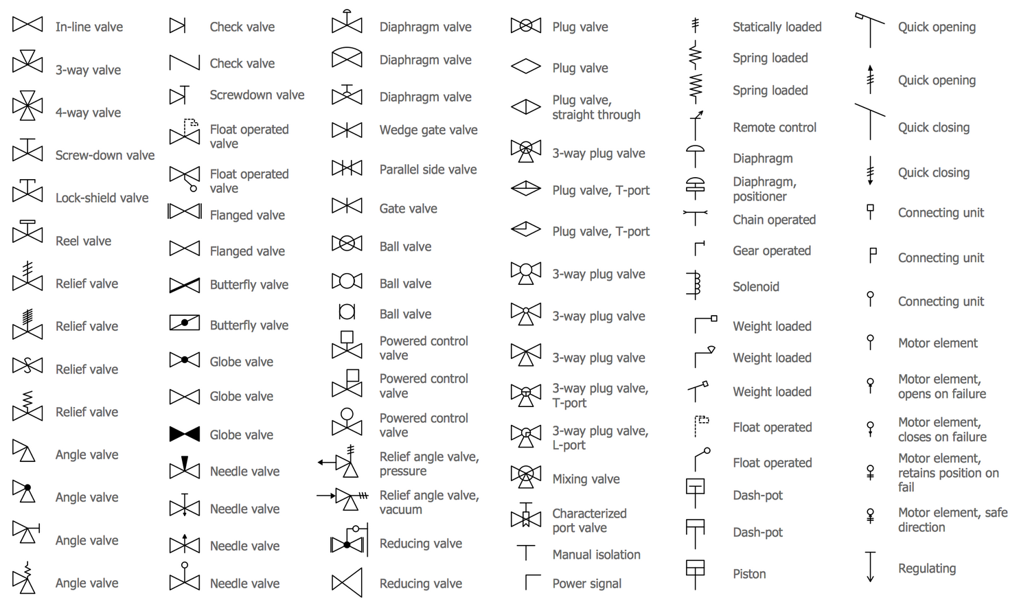
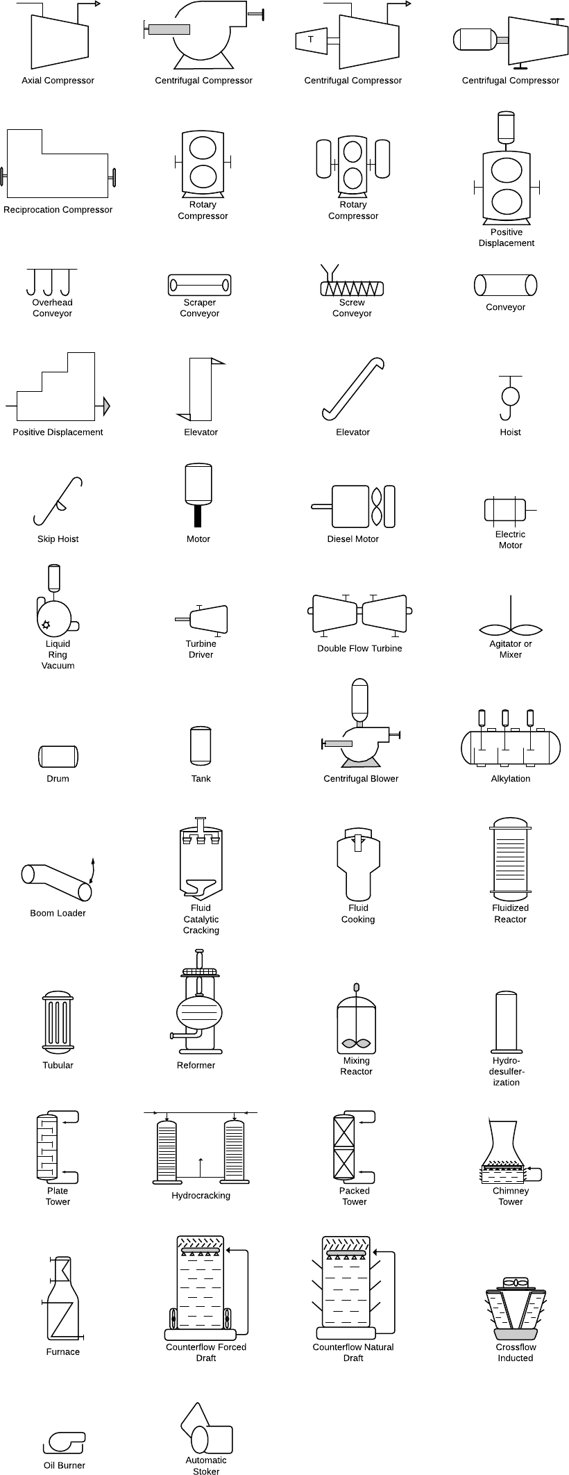
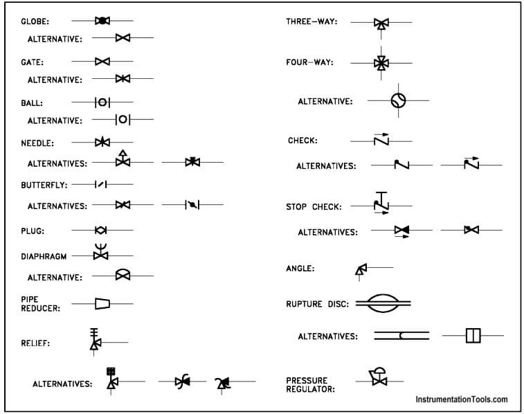
Drawing Symbols For Piping - 1this practice is under the jurisdiction of astm committee f25 on ships and marine technology and is the direct responsibility of subcommittee f25.11 on machinery and piping systems. Web there are few iso and british standards available that provide symbols and best practices to draw pfd and p&id, such as, isa s5.1, bs 5070, and iso 10628. Lighter lines show connected pipe, and are not parts of the symbols. The shapes in this legend are representative of the functional relationship between piping, instrumentation, and system equipment units. Valves are categorized under the following headings: Web piping and instrument diagram standard symbols detailed documentation provides a standard set of shapes & symbols for documenting p&id and pfd, including standard shapes of instrument, valves, pump, heating exchanges, mixers, crushers, vessels, compressors, filters, motors and connecting shapes. Checkout list of such symbols given below. Piping and pipeline drawing symbols throw lights on the type of joint like buttweld, socket weld, or threaded. The symbols for various types of rotary equipment such as a centrifugal pump, vacuum pump, and also positive displacement pumps such as gear and screw types. 2.2 figure 2 provides symbols for valves.
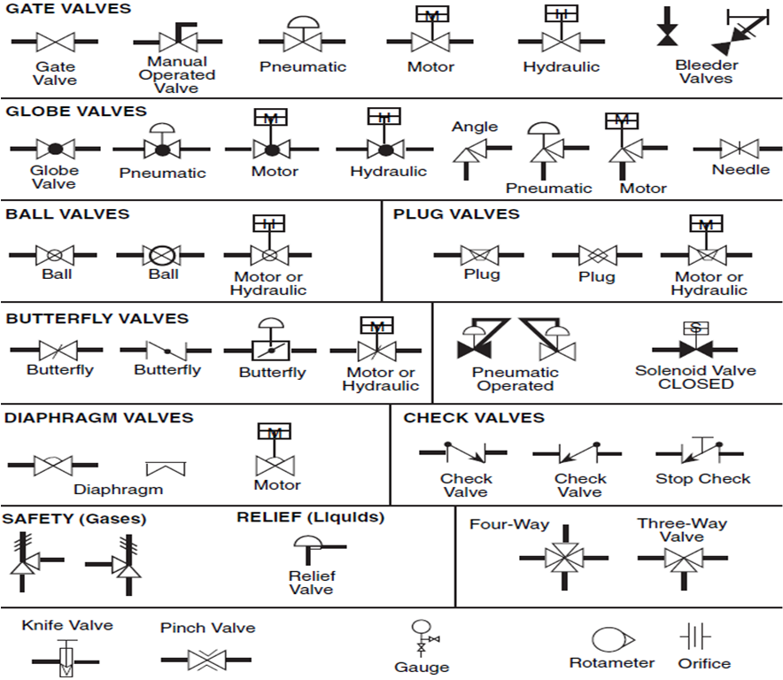
Project number sheet project name project number a3 nps pmis no. 1this practice is under the jurisdiction of astm committee f25 on ships and marine technology and is the direct responsibility of subcommittee f25.11 on machinery and piping systems. Globe, angle, check, ball, butterfly, gate, relief, manifolds, control, noise control, and. Web there are a variety of piping symbols used in metal fabrication drawings, including: This symbol represents a section of pipe that is straight and does not have any bends or curves. 1this practice is under the jurisdiction of astm committee f25 on ships and marine technology and is the direct responsibility of subcommittee f25.11 on machinery and piping systems. Valves are categorized under the following headings: Web there are few iso and british standards available that provide symbols and best practices to draw pfd and p&id, such as, isa s5.1, bs 5070, and iso 10628. This symbol represents a curved section of pipe used to change the direction of the flow. Plumbing plan is connecting pipelines in the walls of a building and underground.
Web there are a variety of piping symbols used in metal fabrication drawings, including: 2.2 figure 2 provides symbols for valves. Web the symbols on these diagrams represent various elements, including: Piping and instrumentation diagrams, or p&ids, are used to create important documentation for process industry facilities. It is available for historical reference only.” Piping and pipeline drawing symbols throw lights on the type of joint like buttweld, socket weld, or threaded. Web there are few iso and british standards available that provide symbols and best practices to draw pfd and p&id, such as, isa s5.1, bs 5070, and iso 10628. Lighter lines show connected pipe, and are not parts of the symbols. Valves are categorized under the following headings: Web a p&id or process and instrumentation diagram provides a detailed graphical representation of the actual process system that includes the piping, equipment, valves, instrumentation, and other process components in the system.
Piping Isometric Drawing Symbols Pdf at Explore
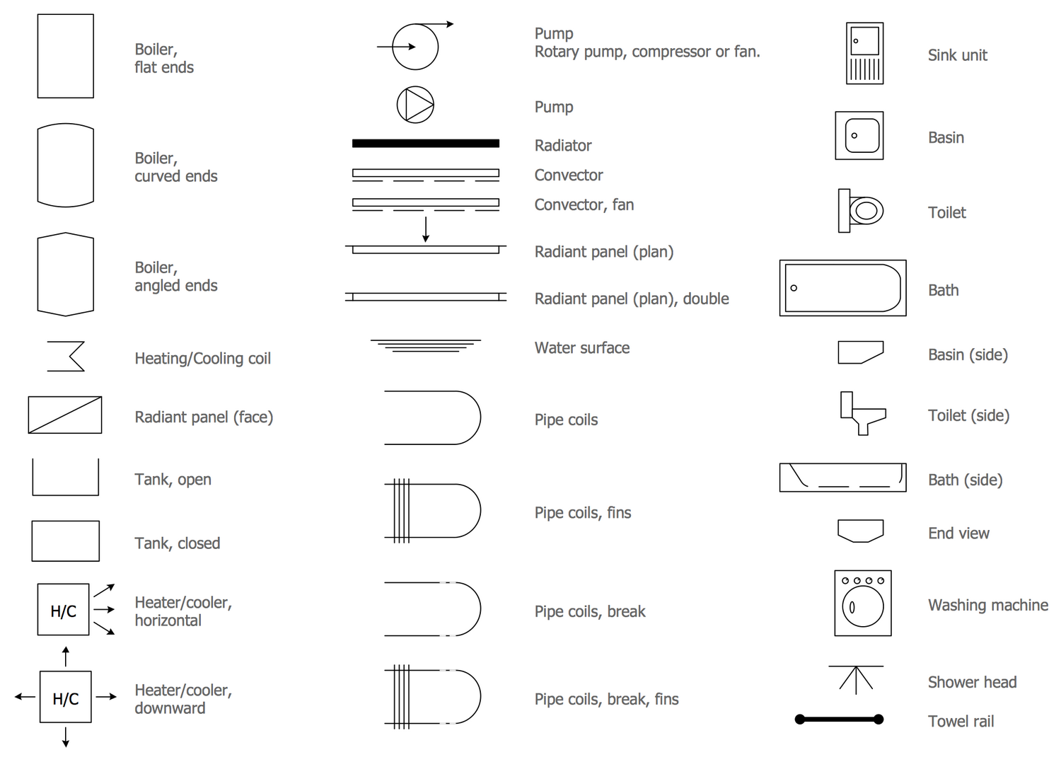
Valves are categorized under the following headings: And abbreviations conventional plan symbols. Web piping and instrument diagram standard symbols detailed documentation provides a standard set of shapes & symbols for documenting p&id and pfd, including standard shapes of instrument, valves, pump, heating exchanges, mixers, crushers, vessels, compressors, filters, motors and connecting shapes. Plumbing plan is connecting pipelines in the walls.
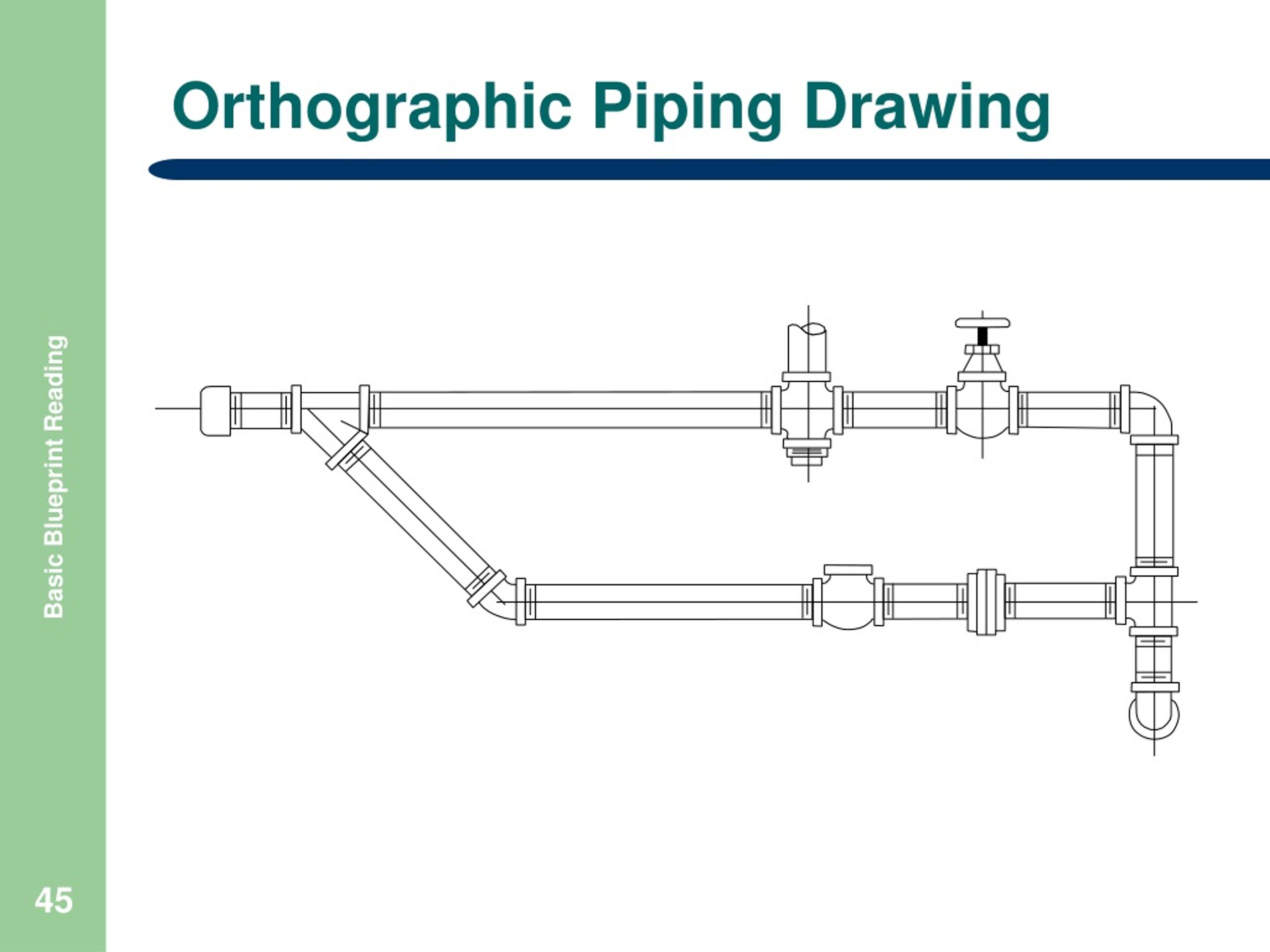
Piping orthographic drawing symbols kloology
Project number sheet project name project number a3 nps pmis no. Symbols are shown in black lines. This symbol represents a section of pipe that is straight and does not have any bends or curves. Current edition approved may 1, 2019. The drawing axes of the isometrics intersect at an angle of 60°.

Piping Isometric Drawings The Piping Engineering World
Web symbols sheet 2 [c:\cadd\sample plans\a sheets\sym(sample).dgn. Web there are a variety of piping symbols used in metal fabrication drawings, including: Web the symbols on these diagrams represent various elements, including: The symbols for various types of rotary equipment such as a centrifugal pump, vacuum pump, and also positive displacement pumps such as gear and screw types. It uses various.
Piping and Instrumentation Diagram Software
All components are represented using various p&id symbols. The shapes in this legend are representative of the functional relationship between piping, instrumentation, and system equipment units. It uses various symbols to represent equipment, piping, instrumentation, and control devices, providing a concise and visual description of. Lighter lines show connected pipe, and are not parts of the symbols. Project number sheet.
Piping Schematic Symbols Pdf
Lines that indicate the direction of flow, along with specifications about the pipe size, material, and number. Web standard practice for piping system drawing symbols. All components are represented using various p&id symbols. Web a p&id or process and instrumentation diagram provides a detailed graphical representation of the actual process system that includes the piping, equipment, valves, instrumentation, and other.

What is Piping Isometric drawing? How to Read Piping Drawing? ALL
It uses various symbols to represent equipment, piping, instrumentation, and control devices, providing a concise and visual description of. 2.2 figure 2 provides symbols for valves. Web piping and instrument diagram standard symbols detailed documentation provides a standard set of shapes & symbols for documenting p&id and pfd, including standard shapes of instrument, valves, pump, heating exchanges, mixers, crushers, vessels,.
Piping Isometric Drawing Symbols Pdf at Explore
What are the plumbing symbols. Checkout list of such symbols given below. Current edition approved may 1, 2019. Piping and instrumentation diagrams, or p&ids, are used to create important documentation for process industry facilities. The drawing axes of the isometrics intersect at an angle of 60°.
Piping Coordination System Mechanical symbols for Isometric drawings
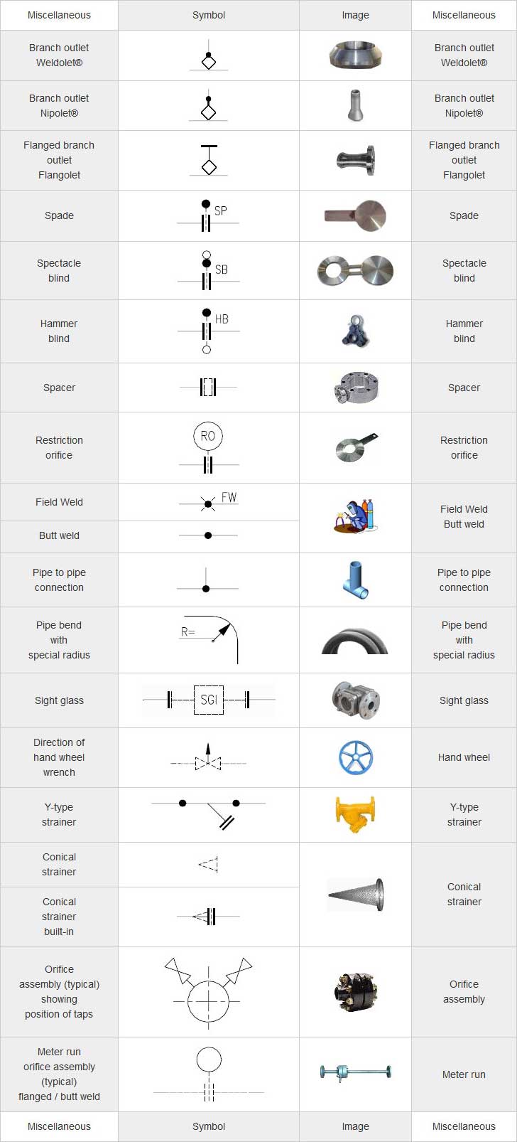
2.1 figure 1 provides symbols for strainers, separators, and filters. Current edition approved may 1, 2019. And abbreviations conventional plan symbols. Web knowing the piping drawing symbols will provide various information like: Web a pipe and instrument diagram (p&id) is a schematic representation of the process flow within a system or plant.
Piping and Instrumentation Symbols Instrumentation Tools
Web the symbols on these diagrams represent various elements, including: Current edition approved june 1, 2021. Pumps and turbine p&id symbols. 1.2 this set of standard symbols is intended for use on piping system diagrammatics and arrangements for ships. 1this practice is under the jurisdiction of astm committee f25 on ships and marine technology and is the direct responsibility of.

standard piping symbols Engineering Feed
This symbol represents a curved section of pipe used to change the direction of the flow. Lines that indicate the direction of flow, along with specifications about the pipe size, material, and number. Web piping and instrumentation diagrams (p&ids) use specific symbols to show the connectivity of equipment, sensors, and valves in a control system. Current edition approved june 1,.
Symbols Are Shown In Black Lines.
This symbol represents a section of pipe that is straight and does not have any bends or curves. Piping and instrumentation diagrams, or p&ids, are used to create important documentation for process industry facilities. Web there are few iso and british standards available that provide symbols and best practices to draw pfd and p&id, such as, isa s5.1, bs 5070, and iso 10628. Checkout list of such symbols given below.
The Shapes In This Legend Are Representative Of The Functional Relationship Between Piping, Instrumentation, And System Equipment Units.
Web a piping isometric drawing is a technical drawing that depicts a pipe spool or a complete pipeline using an isometric representation. Web symbols sheet 2 [c:\cadd\sample plans\a sheets\sym(sample).dgn. Project number sheet project name project number a3 nps pmis no. Lines that indicate the direction of flow, along with specifications about the pipe size, material, and number.
Web Various Symbols Are Used To Indicate Piping Components, Instrumentation, Equipments In Engineering Drawings Such As Piping And Instrumentation Diagram (P&Id), Isometric Drawings, Plot Plan, Equipment Layout, Welding Drawings Etc.
Current edition approved june 1, 2021. Pumps and turbine p&id symbols. Show any project specific abbreviations and symbols here Current edition approved may 1, 2019.
Web Piping And Instrumentation Diagrams (P&Ids) Use Specific Symbols To Show The Connectivity Of Equipment, Sensors, And Valves In A Control System.
Web standard practice for piping system drawing symbols. Isometric symbols for piping fittings. It uses various symbols to represent equipment, piping, instrumentation, and control devices, providing a concise and visual description of. This symbol represents a curved section of pipe used to change the direction of the flow.