Electrical Line Drawing
Electrical Line Drawing - You will become familiar with the many types of diagrams and how to distinguish between them, as well as how to choose the appropriate diagram for a given situation and how to comprehend a logic sequence and a combinatory sequence. Web in summary, a line diagram electrical is a simplified representation of an electrical circuit or system. Web cmes are explosions of plasma and magnetic fields from the sun’s corona. In this post you’ll learn what is single line diagram and why do we need it. It uses standardized symbols to depict various elements such as generators, transformers, switches, motors, and protective devices. Then this article is for you! Web there are three basic types of wiring diagrams: Web line diagram symbols are graphical representations used in electrical circuit diagrams to represent components and connections. Web the electrical drawings consist of electrical outlets, fixtures, switches, lighting, fans, and appliances. Web 2021 / 12 / 01.
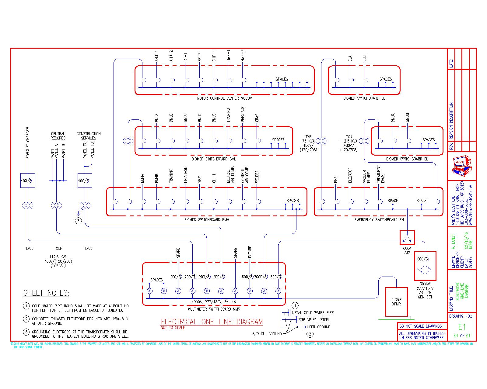
Web single line diagram. Web an electrical single line diagram is a graphical representation of an electrical system’s components and connections. What is a schematic diagram? Wondering how to draw an electrical circuit diagram? Web cmes are explosions of plasma and magnetic fields from the sun’s corona. Smartdraw has several tools and templates for making a variety of visuals for engineering and cad design. Smartdraw comes with thousands of detailed electrical symbols you can drag and. They cause geomagnetic storms when they are directed at earth. Web in summary, a line diagram electrical is a simplified representation of an electrical circuit or system. The diagram is commonly used in designing, operating, and maintaining electrical power systems.
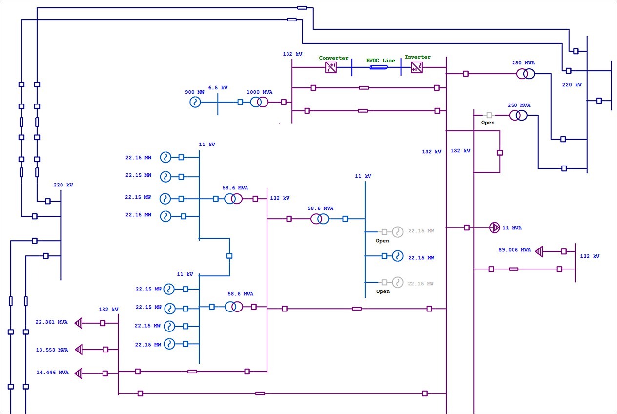
Solidworks electrical schematic professional is a suite of collaborative schematic design tools that drive rapid development of embedded electrical systems. Web we usually depict the electrical distribution system by a graphic representation called a single line diagram (sld). 30k views 11 months ago substation & switchgear. Wondering how to draw an electrical circuit diagram? Web there are three basic types of wiring diagrams: It shows the flow of electrical power from the source to various devices through standardized symbols and lines. The details of an electrical supply from the power source to each electrical equipment in the building are provided on electrical plans. Web line (ladder) diagram is a diagram that shows the logic of an electrical circuit or system using standard symbols. On the file tab, select new, and then search for engineering templates. Among these you'll find commonly used electrical drawings and schematics, like circuit diagrams, wiring diagrams, electrical plans and block diagrams.

Symbols Used In Electrical Schematic Drawing
It shows the flow of electricity through the system using a single line and standardized electrical symbols. Depicts electrical devices as drawings or pictures connected by lines representing wires. Wiring diagrams show specific electrical connections. These symbols are crucial in conveying information about the different elements and their relationships in a circuit. In this video, i'll explain how to read.
Residential Electrical Schematic Diagrams
Web a practical handbook for reading and analysing electrical drawings and diagrams. The details of an electrical supply from the power source to each electrical equipment in the building are provided on electrical plans. Shows how components are related to others on the same circuit, but contains less detailed information about electrical. The diagram is commonly used in designing, operating,.
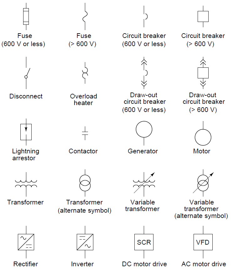
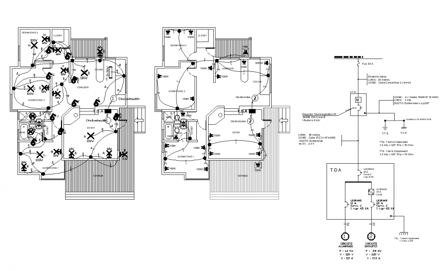
Electrical Line Diagram Symbols
It shows the flow of electrical power from the source to various devices through standardized symbols and lines. Our electrical power systems primarily contain three phases of ac circuits. Let’s see the details provided at different locations of drawings. On the file tab, select new, and then search for engineering templates. Web a circuit diagram allows you to visualize how.
Electrical Drawing at GetDrawings Free download
Web a practical handbook for reading and analysing electrical drawings and diagrams. These symbols are crucial in conveying information about the different elements and their relationships in a circuit. Hv/lv generation, power transmission & distribution of power. Solidworks electrical schematic professional is a suite of collaborative schematic design tools that drive rapid development of embedded electrical systems. Depicts electrical devices.

Electrical power line hand drawn outline doodle Vector Image
Why do you need it? Former champ deontay wilder is the latest to speak out. The diagram is commonly used in designing, operating, and maintaining electrical power systems. Web a circuit diagram allows you to visualize how components of a circuit are laid out. You will become familiar with the many types of diagrams and how to distinguish between them,.

ELECTRICAL LEGEND SINGLE LINE & SCHEMATIC SYMBOLS Free CAD Block And
Web a circuit diagram allows you to visualize how components of a circuit are laid out. They cause geomagnetic storms when they are directed at earth. Line diagrams provide a fast, easy understanding of the connections and use of components. The details of an electrical supply from the power source to each electrical equipment in the building are provided on.

Electrical Drawing Symbols at Explore collection
Web we usually depict the electrical distribution system by a graphic representation called a single line diagram (sld). “a diagram which shows, by means of single lines and graphic symbols, the course of an electric circuit or system of circuits and the component devices or parts used therein.” Web cmes are explosions of plasma and magnetic fields from the sun’s.

How to Draw Electric Field Lines 9 Steps (with Pictures)
Web use the electrical engineering drawing type in visio professional or visio plan 2 to create electrical and electronic schematic diagrams. Then this article is for you! Lines connect fuses, switches, capacitors, inductors, and more. In this video, i'll explain how to read substation single line diagram (sld) in 5 simple steps. Line diagrams provide a fast, easy understanding of.
Single Line Diagram Electrical House Wiring
A single line can show all or part of a system. These symbols are crucial in conveying information about the different elements and their relationships in a circuit. Lines connect fuses, switches, capacitors, inductors, and more. On the file tab, select new, and then search for engineering templates. Wondering how to draw an electrical circuit diagram?

How to Read and Interpret Electrical Shop Drawings Part One
Electrical power grids primarily consist of. Wiring diagrams show specific electrical connections. In this post you’ll learn what is single line diagram and why do we need it. 30k views 11 months ago substation & switchgear. Line diagram is used to show the relationship between circuits and their components but not the actual location of the components.
Web In Summary, A Line Diagram Electrical Is A Simplified Representation Of An Electrical Circuit Or System.
Wondering how to draw an electrical circuit diagram? Web a circuit diagram allows you to visualize how components of a circuit are laid out. The details of an electrical supply from the power source to each electrical equipment in the building are provided on electrical plans. The main thing here is that they rarely (never in my own experience) include the term ‘schematic’.
“A Diagram Which Shows, By Means Of Single Lines And Graphic Symbols, The Course Of An Electric Circuit Or System Of Circuits And The Component Devices Or Parts Used Therein.”
Select one of the following: Electrical power grids primarily consist of. These symbols are crucial in conveying information about the different elements and their relationships in a circuit. Line diagrams provide a fast, easy understanding of the connections and use of components.
Lines Connect Fuses, Switches, Capacitors, Inductors, And More.
Web we usually depict the electrical distribution system by a graphic representation called a single line diagram (sld). Smartdraw comes with thousands of detailed electrical symbols you can drag and. How to draw a circuit diagram? Solidworks electrical schematic professional is a suite of collaborative schematic design tools that drive rapid development of embedded electrical systems.
Why Do You Need It?
Web line (ladder) diagram is a diagram that shows the logic of an electrical circuit or system using standard symbols. Single line diagrams are used in common engineering practice as graphical representation of electrical switchboard or assembly containing more sections, i.e. Web the electrical drawings consist of electrical outlets, fixtures, switches, lighting, fans, and appliances. In this post you’ll learn what is single line diagram and why do we need it.