Electrical Symbols For Drawings
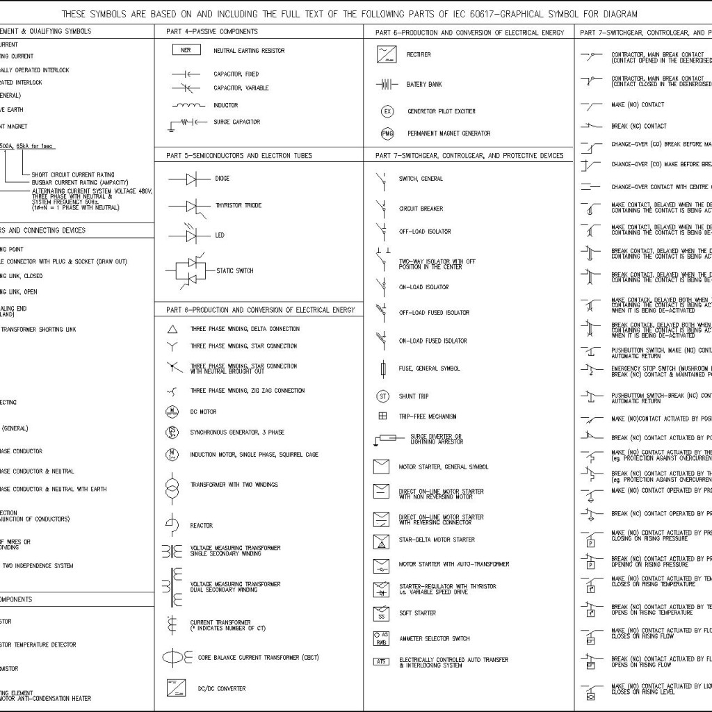
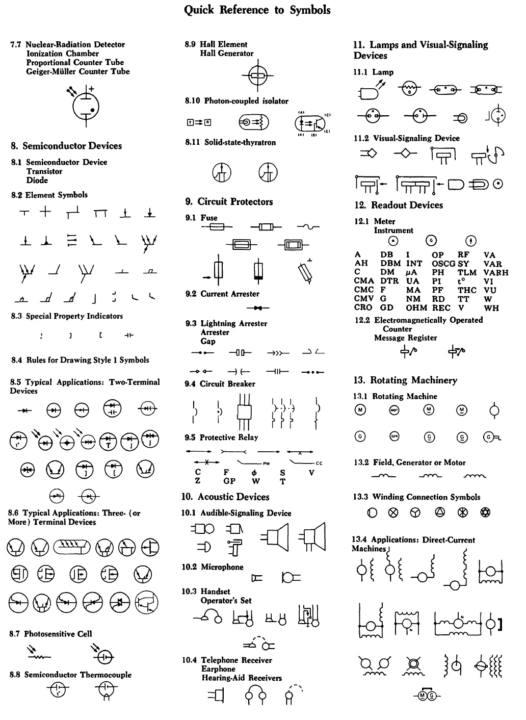
Electrical Symbols For Drawings - The database is the official source of iec 60617. A ground symbol identifies a ground terminal. Represented by two parallel lines. It is also for electrical shock protection. 2 or 3) of the previously published iec 60617 have been incorporated into this database that currently includes some 1900 symbols. Web electrical symbols | electrical drawing symbols. Web common schematic drawing symbols microphone loudspeaker antenna, general symbol machine, general symbol * function m=motor g=generator generator, general symbol indicating instrument, general symbol * function v = voltmeter a = ammeter etc. This article gives some of the frequently used symbols for drawing the circuits. Switches are diagonal lines emanating from the line representing the electrical flow. Web january 15, 2024 by david peterson.
Web iec 60617 contains graphical symbols for use in electrotechnical diagrams. Electrical symbols or electronic circuits are virtually represented by circuit diagrams. Web electrical symbols and electronic circuit symbols are used for drawing schematic diagram. Represented by two parallel lines. Web january 15, 2024 by david peterson. Web you will learn how to define the symbols that should be used according to the type of electrical diagram, clarify the choice of a symbol that should be used on a plan, specify why representation standards are used, and associate a type of standard with a type of symbol through the use of this handbook. The power supply symbol represents a source of electrical energy, such as a battery or a wall outlet. Electrical symbols are visual representations in electrical drawings and diagrams to convey information about components, devices, and connections within a circuit or system. The engineering world is crammed full of drawings and diagrams of every possible kind. Web standard electrical plan symbols are universally accepted representations used to denote specific elements of an electrical system in a diagram or blueprint.
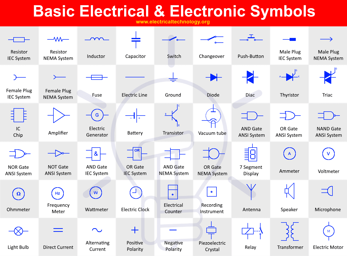
Represented by a zigzag line. Web standard electrical plan symbols are universally accepted representations used to denote specific elements of an electrical system in a diagram or blueprint. Web this basic schematic symbols chart provides a comprehensive overview of the most commonly used symbols in electrical and electronic circuits. A ground symbol identifies a ground terminal. Each physical component (i.e resistor, capacitor, transistor) has a unique schematic symbol. You can depict a complex electrical circuit with the standard and simplified electrical symbols. 2 or 3) of the previously published iec 60617 have been incorporated into this database that currently includes some 1900 symbols. Capacitors (parallel lines) store energy in your system, while. Frequently occurring technical phrases are commonly rendered as abbreviations (such as e.m.f., p.d.). Web some common symbols used in wiring diagrams include:
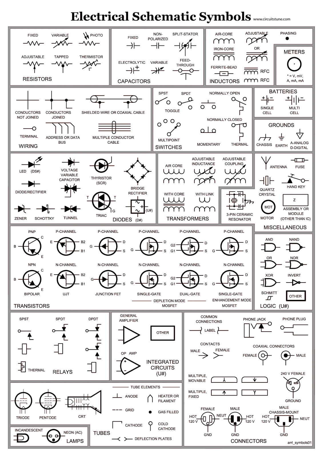
Electrical Schematic Symbols CircuitsTune
Web some common symbols used in wiring diagrams include: Represented by various shapes depending on the type (e.g., npn or pnp) A ground symbol identifies a ground terminal. The engineering world is crammed full of drawings and diagrams of every possible kind. Web common circuit diagram symbols (us ansi symbols) an electronic symbol is a pictogram used to represent various.

Electrical Drawing Symbols at Explore collection
Web you will learn how to define the symbols that should be used according to the type of electrical diagram, clarify the choice of a symbol that should be used on a plan, specify why representation standards are used, and associate a type of standard with a type of symbol through the use of this handbook. Web basic electrical symbols.
Electrical Symbols Electrical Drawing Symbols Electrical Academia
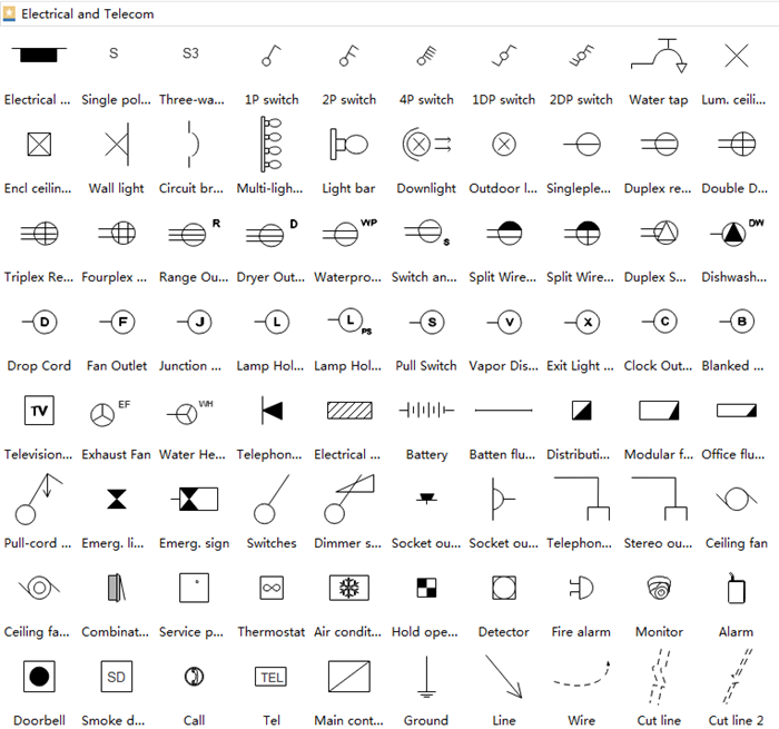
In circuit diagrams, graphical symbols identify network components and devices. Switches are diagonal lines emanating from the line representing the electrical flow. Web electrical symbols | electrical drawing symbols. Web electrical symbols are the most commonly used symbols in circuit diagramming. Whether you are a novice or a professional engineer, these basic symbols can help create accurate electrical and circuit.
Electrical drawing symbols in autocad jesdesk
Web diagrams showing electrical flow through a circuit use standardized symbols to represent electrical components. You can depict a complex electrical circuit with the standard and simplified electrical symbols. Represented by a zigzag line. Web electrical symbols | electrical drawing symbols. Frequently occurring technical phrases are commonly rendered as abbreviations (such as e.m.f., p.d.).
Electrical Drawing Symbols at Explore collection
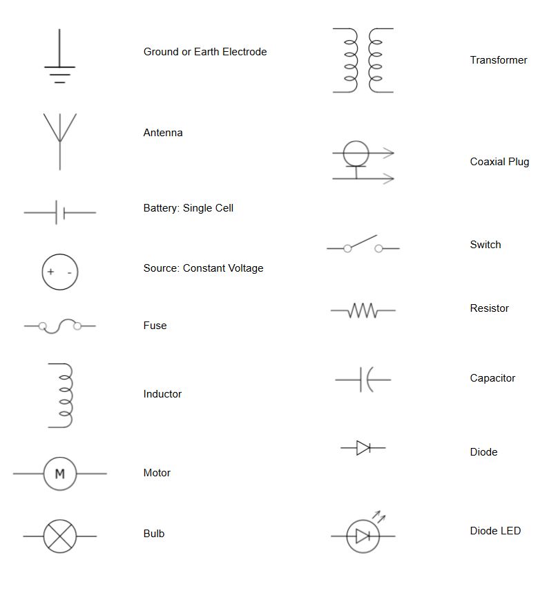
In circuit diagrams, graphical symbols identify network components and devices. Web january 15, 2024 by david peterson. You can depict a complex electrical circuit with the standard and simplified electrical symbols. The symbols represent electrical and electronic components. Web here is a list of some basic electrical symbols commonly used in schematic diagrams:
Electrical Drawing Symbols at Explore collection
It can be used for a zero potential reference point from where current is measured. There are some standard symbols to represent the components in a circuits. Every engineering office uses their own set of electrical symbols; Web you will learn how to define the symbols that should be used according to the type of electrical diagram, clarify the choice.
Electrical Symbols ClipArt ETC
The symbols represent electrical and electronic components. Web basic electrical symbols contain earth electrode, cell, battery, resistor, etc. Electrical symbols or electronic circuits are virtually represented by circuit diagrams. Web create your circuit diagram. Web some commonly used symbols in an electrical schematic symbols chart include:
Basic & Important Electrical Symbols and Electronic Symbols
To start developing your schematic reading abilities, it’s important to memorize the most common schematic symbols. Each physical component (i.e resistor, capacitor, transistor) has a unique schematic symbol. Web you will learn how to define the symbols that should be used according to the type of electrical diagram, clarify the choice of a symbol that should be used on a.

Free CAD Blocks Electrical Symbols
Represented by a zigzag line. There are some standard symbols to represent the components in a circuits. Web common schematic drawing symbols microphone loudspeaker antenna, general symbol machine, general symbol * function m=motor g=generator generator, general symbol indicating instrument, general symbol * function v = voltmeter a = ammeter etc. These icons serve as a standardized and universally recognized language.
How to Read and Interpret Electrical Shop Drawings Part Two
To start developing your schematic reading abilities, it’s important to memorize the most common schematic symbols. Web standard electrical plan symbols are universally accepted representations used to denote specific elements of an electrical system in a diagram or blueprint. On electrical or electronic diagrams, symbols are used to represent electrical components. The power supply symbol represents a source of electrical.
These Symbols Are Used In Engineering Drawings, Wiring Schematics, Circuit Diagrams, And Architectural Blueprints.
Web common circuit diagram symbols (us ansi symbols) an electronic symbol is a pictogram used to represent various electrical and electronic devices or functions, such as wires, batteries, resistors, and transistors, in a schematic. Web create your circuit diagram. Web symbols (such as j, exp, cu) are used to indicate mathematical operations, chemical elements etc. Amplifiers (denoted by triangle shapes) increase the output signal in your circuit.
These Icons Serve As A Standardized And Universally Recognized Language That Engineers, Electricians, And Technicians Use To Communicate And Understand.
Web this basic schematic symbols chart provides a comprehensive overview of the most commonly used symbols in electrical and electronic circuits. Web some commonly used symbols in an electrical schematic symbols chart include: It can be used for a zero potential reference point from where current is measured. Web the ability to read electrical schematics is a really useful skill to have.
A Ground Symbol Identifies A Ground Terminal.
It is typically depicted as a circle or a rectangle with a plus and minus sign indicating the positive and negative terminals. Web january 15, 2024 by david peterson. Represented by various shapes depending on the type (e.g., npn or pnp) You can depict a complex electrical circuit with the standard and simplified electrical symbols.
The Symbols Represent Electrical And Electronic Components.
Web electrical symbols | electrical drawing symbols. However, the symbols below are fairly common across many offices. Each physical component (i.e resistor, capacitor, transistor) has a unique schematic symbol. Web basic electrical and electronic graphical symbols called schematic symbols are commonly used within circuit diagrams, schematics and computer aided drawing packages to identify the position of individual components and elements within a circuit.