Engineer Drawing Scale
Engineer Drawing Scale - Help make archtoolbox better for everyone. Web engineer scales are tailored for technical drawings and engineering projects. Web how to read an engineers scale (mostly used for roads and topographical measurements) engineer scales, such as 1˝ = 10´ or 1˝ = 50´ how to read a metric scale (mostly used for buildings in other parts of the world) how to determine the scale of a drawing where the scale isn’t indicated. Instead, instruments called scales are employed. A scale is the ratio of the linear dimension of an object’s element as shown in a drawing to the actual dimensions of the same object’s element. Engine · rotring · strollers · celestron · equestrian From roads to railways, an engineer scale’s multiple ratios accommodate complex projects that demand precise measurements. Web in this lesson, i will demonstrate how to use an architect’s and an engineer’s scale for drawing landscape design plans to proper scale. The trick is to use the scale factor, which appears in our cad scale factors article. They help in conveying the dimensions and proportions of the objects accurately.
Help make archtoolbox better for everyone. Web in this lesson, i will demonstrate how to use an architect’s and an engineer’s scale for drawing landscape design plans to proper scale. The proportion by which we either reduce or increase the actual size of the object on a drawing is known as scale. Blueprint drawings are typically drawn in. For example, if the scale of the drawing is 1 inch = 20 feet, you would use the 1:20 side of the scale. The scale and the size of the object in turn, will decide the size of the drawing. If a drawing is drawn to scale, it can be used to obtain information such as physical dimensions, tolerances, and materials that allows the fabrication or construction of the component or system. Be sure to check out our article, converting between drawing scales, if you need to manually change the scale of a drawing or object. Web given an architect or engineer scale and a set of scaled drawings, you will be able to select the correct scale (tool) and interpret dimensions with 100% accuracy. The recommended scales for use on technical drawings are given in table.
Blueprint drawings are typically drawn in. When representing assemblies or parts, it is often necessary to draw the assemblies or parts larger or smaller. Be sure to check out our article, converting between drawing scales, if you need to manually change the scale of a drawing or object. Where the denominator is the number after the colon. Web this is drafting tools 101in this series we will discuss the tools used in drawing and drafting. Engine · rotring · strollers · celestron · equestrian Web the scale in engineering drawings represents the size of objects in a reduced or enlarged format. It is a very common tool used for measuring things in land development and site construction plans. This basic skill will help you understand and read technical engineering drawings scaled. Web engineer scales are tailored for technical drawings and engineering projects.

Understanding Scales and Scale Drawings A Guide
1/4 or 1/8 (imperial units, us) scales. Label the scale clearly showing meters, decimeters and centimeters. Web given an architect or engineer scale and a set of scaled drawings, you will be able to select the correct scale (tool) and interpret dimensions with 100% accuracy. When representing assemblies or parts, it is often necessary to draw the assemblies or parts.

Best Architect’s Ruler for Drawing and Drafting
Once you know the scale, select the appropriate side of the engineer’s scale. Web the designation of the scale used on the drawing should be shown in the title block. Most cad systems allow the drafter to draw at whatever scale he or she feels like. Web the scale in engineering drawings represents the size of objects in a reduced.

PREMIUM 12 inch Triangular Engineer Scale Ruler Anodized Solid Aluminum
You will be able to identify the diference. Label the scale clearly showing meters, decimeters and centimeters. They help in conveying the dimensions and proportions of the objects accurately. Because engineering drawings are not always drawn full size, ordinary rulers are not usually used for manual drafting. A scale is the ratio of the linear dimension of an object’s element.

How To Make A Scale Drawing in Engineering. YouTube
Web professional drafting scales, engineering scales, and architectural scales can come in a number of sizes and models. Why choose the engineer scale? In this post we will be exploring architectural scales and scale drawings. Instead, instruments called scales are employed. They help in conveying the dimensions and proportions of the objects accurately.

What is a Scale of a drawing Theory of Scales in Engineering Drawing
Where the denominator is the number after the colon. Be sure to check out our article, converting between drawing scales, if you need to manually change the scale of a drawing or object. Scales are precision instruments with fine graduations or marks. Web learn how to read the various scales and then how to use the scale on a couple.
"types of scale in engineering drawing" "standard engineering drawing
Web professional drafting scales, engineering scales, and architectural scales can come in a number of sizes and models. Because engineering drawings are not always drawn full size, ordinary rulers are not usually used for manual drafting. This is usually printed on the drawing. Most cad systems allow the drafter to draw at whatever scale he or she feels like. Web.
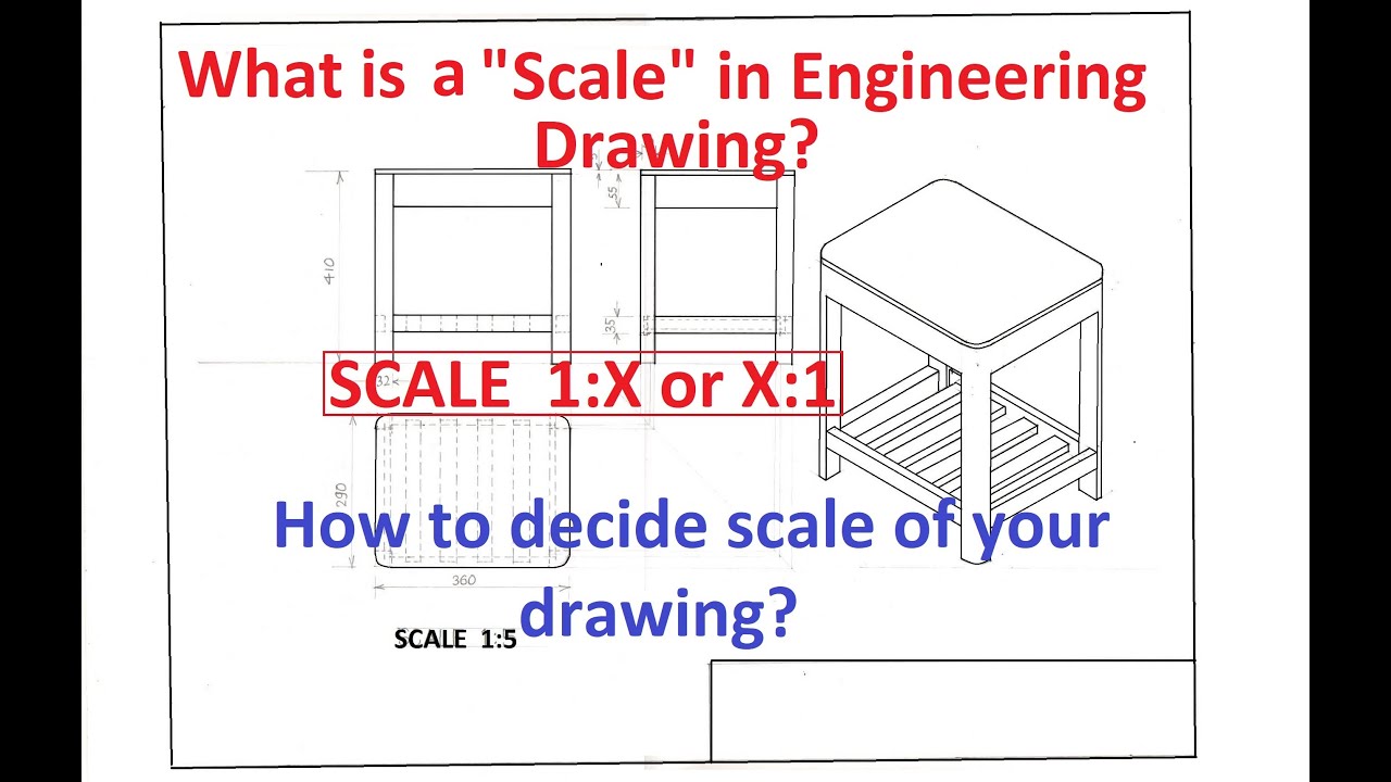
1.8What is a "Scale" in Engineering Drawing? How to decide scale of
Web the scale in engineering drawings represents the size of objects in a reduced or enlarged format. This basic skill will help you understand and read technical engineering drawings scaled. Web the designation of the scale used on the drawing should be shown in the title block. The scale factor is used to compare the scales to each other. The.

plain scale in engineering drawing scales in engineering drawing
Web learn how to read the various scales and then how to use the scale on a couple of simple examples. Web what is scale in engineering drawing? Because engineering drawings are not always drawn full size, ordinary rulers are not usually used for manual drafting. They help in conveying the dimensions and proportions of the objects accurately. Web an.
Mechanical Drawing Scales Tutorial Engineering Drawing Basics
Web the scale in engineering drawings represents the size of objects in a reduced or enlarged format. You can even find a metric scale if that’s what you need. Web the designation of the scale used on the drawing should be shown in the title block. Web how to read an engineers scale (mostly used for roads and topographical measurements).

Engineering Scales and Equivalents Chart Convert to Autocad
They help in conveying the dimensions and proportions of the objects accurately. The recommended scales for use on technical drawings are given in table. When representing assemblies or parts, it is often necessary to draw the assemblies or parts larger or smaller. Web learn how to read the various scales and then how to use the scale on a couple.
Multiply The Measurement On The Drawing With The Denominator.
For example, if the scale of the drawing is 1 inch = 20 feet, you would use the 1:20 side of the scale. In this episode you'll learn everything you need to know abo. Web the scale in engineering drawings represents the size of objects in a reduced or enlarged format. However, if fabrication shops are going to be using your drawings you will help them far more by drawing views to commonly accepted engineering and architectural scales.
You Will Be Able To Identify The Diference.
Web how to read an engineers scale (mostly used for roads and topographical measurements) engineer scales, such as 1˝ = 10´ or 1˝ = 50´ how to read a metric scale (mostly used for buildings in other parts of the world) how to determine the scale of a drawing where the scale isn’t indicated. The scale factor is used to compare the scales to each other. Or, a scale is a measuring device that is used to determine a person’s weight. Web an engineering scale is basically an advanced ruler designed for determining linear measurements in technical drawings.
Scales Are Precision Instruments With Fine Graduations Or Marks.
Instead, instruments called scales are employed. Web common graduations on an engineer scale include 1:10, 1:20, and 1:50, allowing users to precisely depict structures, layouts, and systems in meticulous detail. The recommended scales for use on technical drawings are given in table. Blueprint drawings are typically drawn in.
Web Learn How To Read The Various Scales And Then How To Use The Scale On A Couple Of Simple Examples.
Web given an architect or engineer scale and a set of scaled drawings, you will be able to select the correct scale (tool) and interpret dimensions with 100% accuracy. A scale is the ratio of the linear dimension of an object’s element as shown in a drawing to the actual dimensions of the same object’s element. Most cad systems allow the drafter to draw at whatever scale he or she feels like. The scale and the size of the object in turn, will decide the size of the drawing.