Engineering Drawing Details
Engineering Drawing Details - Web engineering drawing abbreviations and symbols are used to communicate and detail the characteristics of an engineering drawing. The mechanical engineering branch, mechanical systems division, has been delegated Compared to verbal or written descriptions, this method is brief and clearer. Web detail drawings are an essential aspect of engineering, architecture, and the construction industry as a whole. Engineering drawing is a critical part of almost all engineering projects. Civil engineering drawings are the bedrock of any construction project, acting as the visual roadmap that guides engineers, architects, and construction teams toward successful project completion. Web although engineers created the engineering drawings in the past by hand, today, they are primarily done in cad software like autodesk fusion 360. Do not dimension the drawing. [4] the name and contact information for the company producing or distributing the part. An engineering drawing is a subcategory of technical drawings.
All the information on the drawing should be clear and precises and nothing should be left for interpretation. Web an engineering drawing is a type of technical drawing that is used to convey information about an object. They provide a detailed description of the geometric form of an object’s part, such as a building, bridge, tunnel, machine, plant, and more. A common use is to specify the geometry necessary for the construction of a component and is called a detail drawing. If you find any mistakes, missing information or have a question, contact: Web engineering drawings serve as the backbone of various industries, providing a visual representation of designs, dimensions, and specifications. Web engineering drawing is the practice of applying precise measurements and guidelines to depict the structure, dimensions, and other technical details of an object or system. The top cad programs provide an array of precision tools to ensure that every line, curve, and angle is exact. A complete understanding of the object should be possible from the drawing. Import) a 3d model, and then we start inserting the views in the drawing and adding dimensions.
This list includes abbreviations common to the vocabulary of people who work with engineering drawings in the manufacture and inspection of parts and assemblies. Tdot cadd support 1200 james k. Creating drawings using the cad software is a straightforward process; We can find that engineering drawing serves many critical applications: Usually prepared by the design team or contractors, these drawings emphasize the authentic construction details for final project acceptance and archival. Proposed changes by dod activities must be submitted to the dod adopting activity: Compared to verbal or written descriptions, this method is brief and clearer. Web engineering working drawings basics page 8 of 22 parallel to the object surface. Web an engineering drawing is a type of technical drawing that is used to convey information about an object. The top cad programs provide an array of precision tools to ensure that every line, curve, and angle is exact.
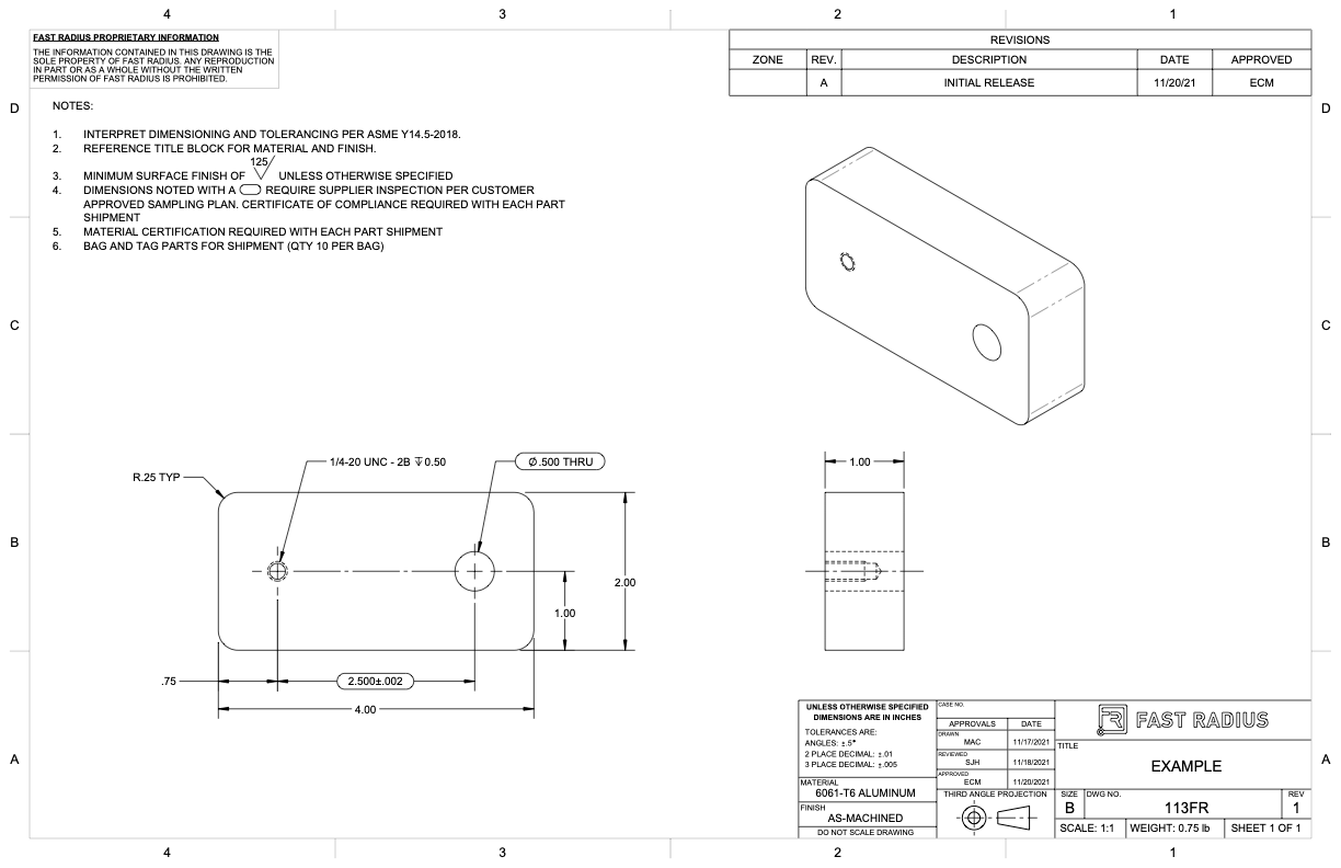
What to Include in Your Engineering Drawing Fast Radius
Web engineering drawing abbreviations and symbols are used to communicate and detail the characteristics of an engineering drawing. Web asme y14.24, “drawings types and applications of engineering drawings”, was adopted on. Web any engineering drawing should show everything: Web engineering drawing is a specialized form of communication that uses a strict set of symbols, standards, and perspectives to depict mechanical,.

How to prepare a technical drawing for CNC machining 3D Hubs
Web detail drawings are an essential aspect of engineering, architecture, and the construction industry as a whole. If the isometric drawing can show all details and all dimensions on one drawing, it is ideal. If you find any mistakes, missing information or have a question, contact: Web engineering drawing is a specialized form of communication that uses a strict set.
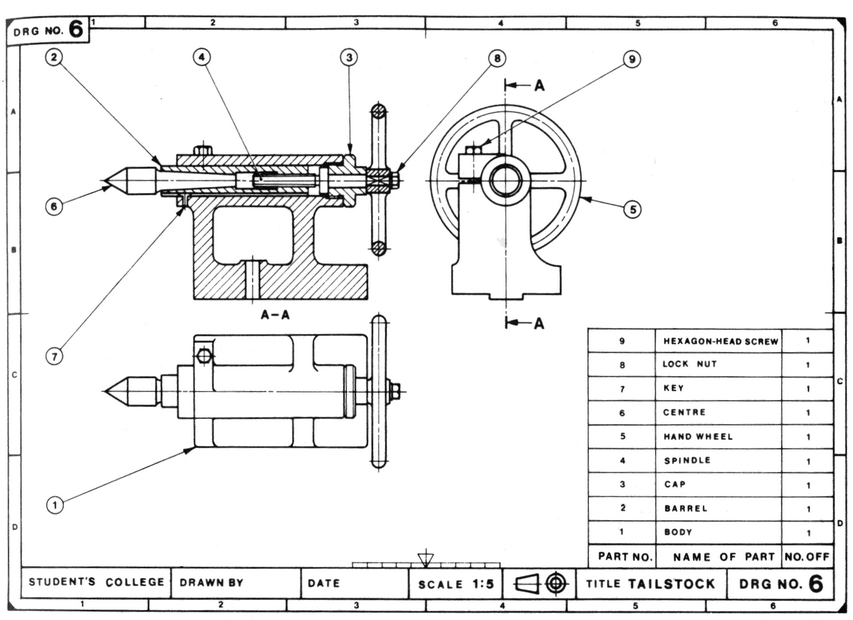
Lecture Notes Engineering Drawing Part 5
Web students are introduced to detail drawings and the importance of clearly documenting and communicating their designs. Engineering drawing is a critical part of almost all engineering projects. Web archived standard drawings. Tdot cadd support 1200 james k. Import) a 3d model, and then we start inserting the views in the drawing and adding dimensions.
How To Prepare A Perfect Technical Drawing Xometry Europe
They provide a detailed description of the geometric form of an object’s part, such as a building, bridge, tunnel, machine, plant, and more. A complete understanding of the object should be possible from the drawing. Engineering drawings use standardised language and symbols. A complete understanding of the object should be possible from the drawing. Web 3 precision tools.
Engineering Drawing at GetDrawings Free download
Stormy daniels' testimony in donald trump’s hush money trial tuesday including plenty of details but it was the court artist's sketch of the former adult film star that captured the. Web engineering drawing abbreviations and symbols are used to communicate and detail the characteristics of an engineering drawing. One can pack a great deal of information into an isometric drawing..

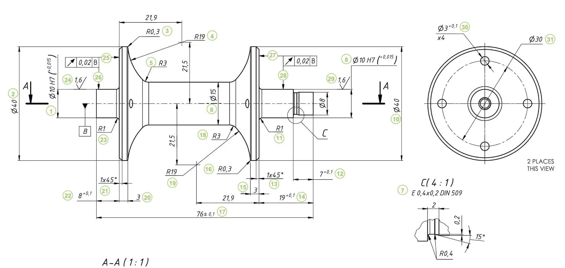
2D Technical Drawings CNC Machining Service
They are introduced to the american national standards institute (ansi) y14.5 standard, which controls how engineers communicate and archive design information. This list includes abbreviations common to the vocabulary of people who work with engineering drawings in the manufacture and inspection of parts and assemblies. Proposed changes by dod activities must be submitted to the dod adopting activity: It is.
Engineering Drawing Views & Basics Explained Fractory
Web engineering drawings serve as the backbone of various industries, providing a visual representation of designs, dimensions, and specifications. One can pack a great deal of information into an isometric drawing. If you find any mistakes, missing information or have a question, contact: Web asme y14.24, “drawings types and applications of engineering drawings”, was adopted on. Web engineering drawing is.

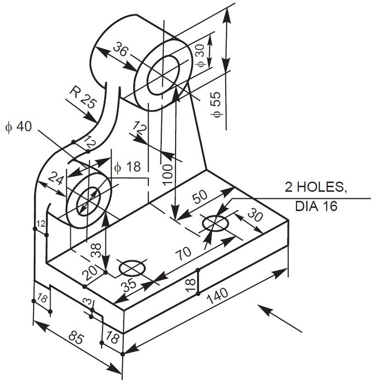
Mechanical Engineering Drawing and Design, Everything You Need To Know
Tdot cadd support 1200 james k. Any engineering drawing should show everything: It is an axonometric projection in which the three coordinate axes appear equally foreshortened and the angle between any two of them is 120 degrees. Web task 5.6 convert the orthographic drawing shown below into an isometric drawings. 14 february 2000 for use by the department of defense.
Engineering Drawing Views & Basics Explained Fractory
The title block appears either at the top or bottom of an engineering drawing. Web unlike a 3d model, an engineering drawing offers a lot more specific information and requirements, including: If the isometric drawing can show all details and all dimensions on one drawing, it is ideal. If you find any mistakes, missing information or have a question, contact:.

how to read civil engineering drawings Engineering Feed
Therefore, any surface that is not in line with the three major axis needs its own projection plane to show the features correctly. Any engineering drawing should show everything: But as we are using cad software to create the drawings, cad software has already implemented iso rules. They provide a detailed description of the geometric form of an object’s part,.
Web Engineering Drawings Serve As The Backbone Of Various Industries, Providing A Visual Representation Of Designs, Dimensions, And Specifications.
Turf reinforcement mat for channel installation. Web an engineering drawing is a type of technical drawing that is used to convey information about an object. This makes understanding the drawings simple with little to no personal. Read this first to find out crucial information about the drawing, including:
Import) A 3D Model, And Then We Start Inserting The Views In The Drawing And Adding Dimensions.
It is used in ships for navigation. They are introduced to standard paper. The top cad programs provide an array of precision tools to ensure that every line, curve, and angle is exact. A good rule to remember is that the person drafting or creating the drawing is the link between the inventor / designer and the manufacturer.
A Complete Understanding Of The Object Should Be Possible From The Drawing.
Proposed changes by dod activities must be submitted to the dod adopting activity: The mechanical engineering branch, mechanical systems division, has been delegated Web although engineers created the engineering drawings in the past by hand, today, they are primarily done in cad software like autodesk fusion 360. Web task 5.6 convert the orthographic drawing shown below into an isometric drawings.
[4] The Name And Contact Information For The Company Producing Or Distributing The Part.
But as we are using cad software to create the drawings, cad software has already implemented iso rules. Do not dimension the drawing. Web detail drawings are an essential aspect of engineering, architecture, and the construction industry as a whole. All the information on the drawing should be clear and precises and nothing should be left for interpretation.