Engineering Drawing Projection Views
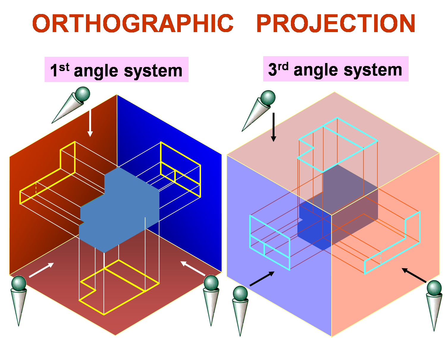
Engineering Drawing Projection Views - This method can be used with both simple and complex objects and involves the use of a cutting plane that dictates what portion of the object you want to remove to reveal a more complex interior. Web by gd&t basics on march 30, 2021. The 1st angle projection system is popular in european countries, whereas 3rd angle projection is popular in north america and asian countries. Isometric projection | concept and objective problems | engineering drawing | ese prelims |. It controls the scale, orientation, and location of the views projected from it. In most cases, a single view is not sufficient to show all necessary features, and several views are. Web the main elements of the section view are: How the views are laid out on a drawing depends on whether 3 rd angle or 1 st angle projection is being used. Web introduction to geometric projections and projected views different types of projections parallel perspective orthographic projection views first angle third angle techniques for drawing orthographic projections Web section views are used extensively to show features of an object or an assembly that are not easily visible from the exterior.
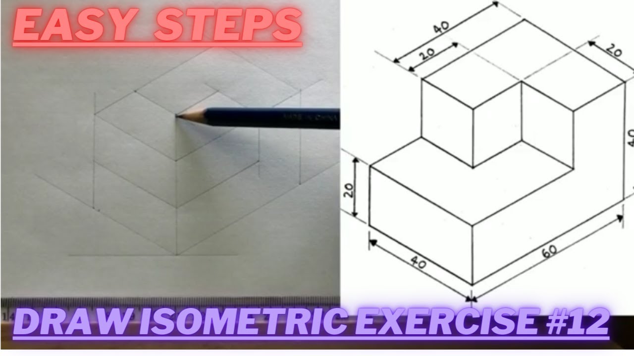
Web the front view of the cube, therefore, represents its isometric projection. It controls the scale, orientation, and location of the views projected from it. Web several types of graphical projection compared various projections and how they are produced isometric view of the object shown in the engineering drawing below. The two main types of views (or “projections”) used in drawings are: Section line, section reference arrow, section reference letters, hatch. This comprehensive guide explains projections and how they are used to create accurate representations of designs in engineering. Web the two main types of views (or “projections”) used in drawings are: Web in this comprehensive tutorial, we delve into the art of creating flawless isometric views using orthographic projections. Web by gd&t basics on march 30, 2021. The representation of the object in figure 2 is called an isometric drawing.
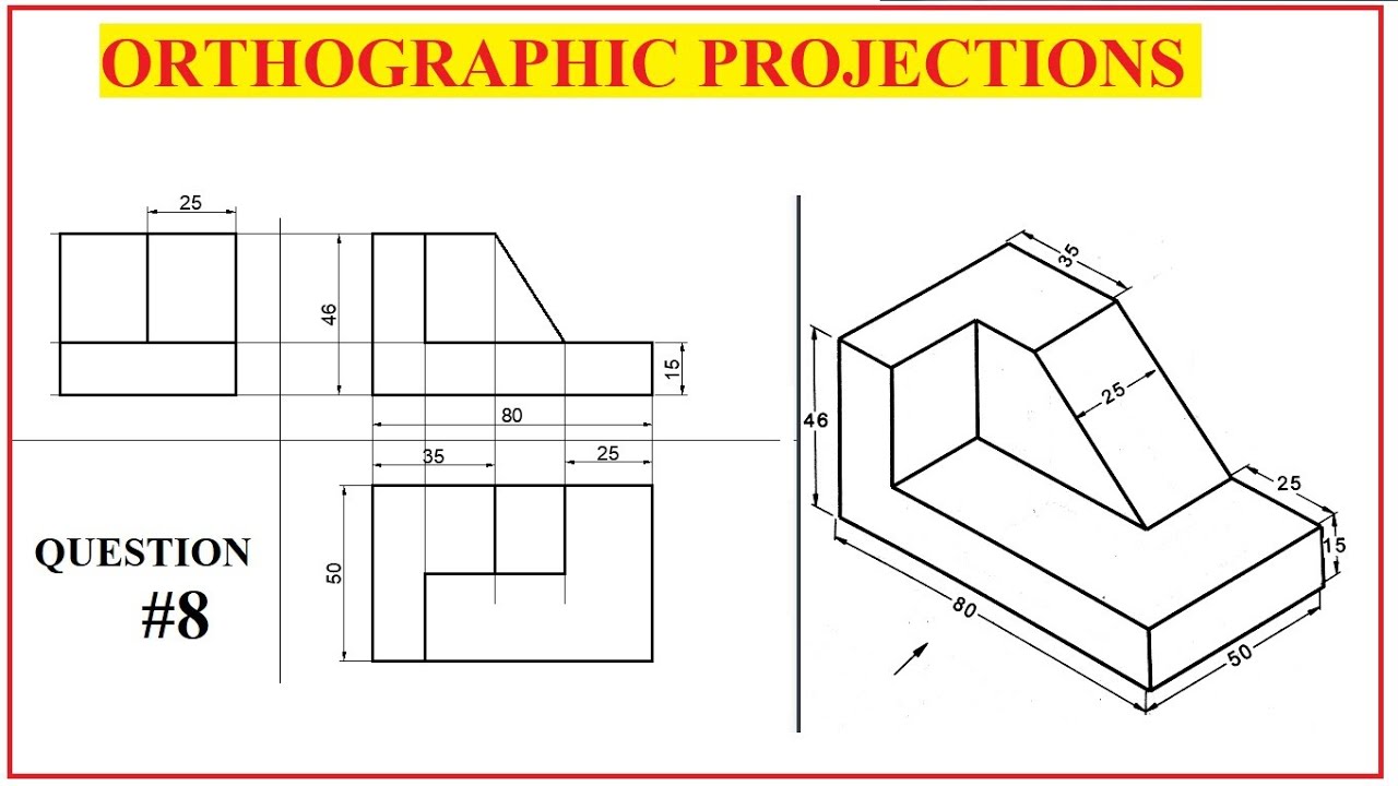
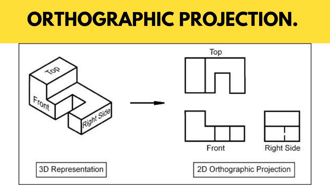
Web by gd&t basics on march 30, 2021. The orthographic and/or isometric views in the drawing are created from the base view. To find the length of the edges in the isometric projection: Web understanding the types, principles, and significance of engineering drawing views empowers engineers and designers to communicate design intent effectively, visualize complex geometries accurately, and ensure manufacturability and compliance with industry standards. The width dimension is common to the front and top views. This comprehensive guide explains projections and how they are used to create accurate representations of designs in engineering. More than one view of an object is drawn to represent it in true sizes and shapes. Orthographic views allow us to represent a 3d object in 2d on a drawing. Web types of views used in drawings. Isometric projection | concept and objective problems | engineering drawing | ese prelims |.

Basic Engineering Drawing Projection Knowledge Zone, The Online Support
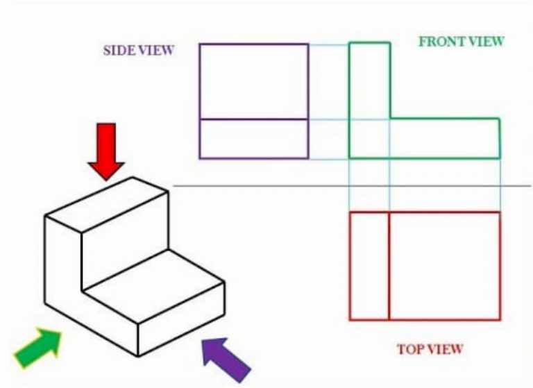
The width dimension is common to the front and top views. Web first angle and third angle projection are the types of orthographic projection systems to draw engineering drawings. Web the main elements of the section view are: Orthographic views allow us to represent a 3d object in 2d on a drawing. It controls the scale, orientation, and location of.
?What do you know about the engineering drawing « Ali's Engineering Design
More than one view of an object is drawn to represent it in true sizes and shapes. Web a base view is the first view created on the drawing sheet. Web the two main types of views (or “projections”) used in drawings are: The representation of the object in figure 2 is called an isometric drawing. This will allow you.
How to draw ISOMETRIC PROJECTIONS Technical Drawing Exercise 12
The width dimension is common to the front and top views. Web section views are used extensively to show features of an object or an assembly that are not easily visible from the exterior. Edges or boundaries which are obscured (not visible from the chosen viewing direction) are shown with dashed lines. The height dimension is common to the front.
ORTHOGRAPHIC PROJECTION IN ENGINEERING DRAWING YouTube
This is even truer for engineers and machinists. In most cases, a single view is not sufficient to show all necessary features, and several views are. Web types of views used in drawings. Web first angle and third angle projection are the types of orthographic projection systems to draw engineering drawings. Whether you're a seasoned engineer or just starting your.
Engineering Drawing Views & Basics Explained Fractory
It controls the scale, orientation, and location of the views projected from it. This method can be used with both simple and complex objects and involves the use of a cutting plane that dictates what portion of the object you want to remove to reveal a more complex interior. Web in this comprehensive tutorial, we delve into the art of.

Basic Engineering Drawing Projection Knowledge Zone, The Online Support
Web want to master engineering drawings? Web types of views used in drawings. Drawings and pictures are among the best means of communicating one’s ideas and views. This will allow you to communicate the intent of your design for cnc machined parts. This method can be used with both simple and complex objects and involves the use of a cutting.
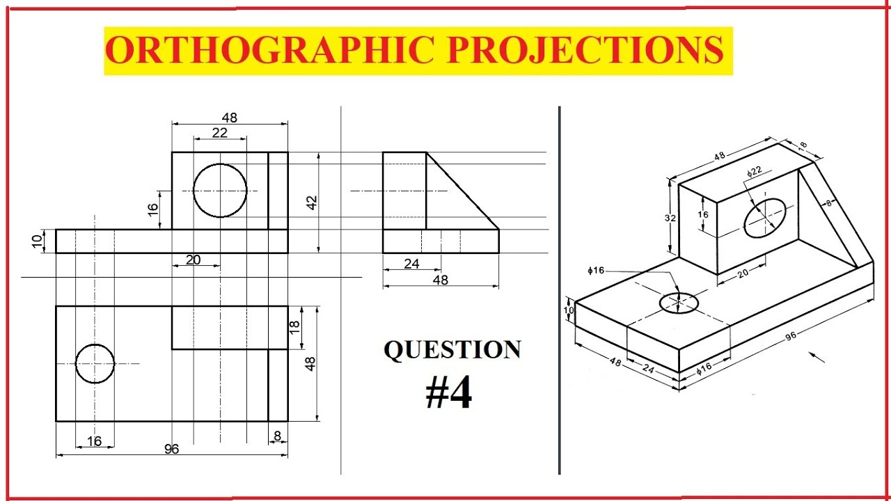
Orthographic Projection, Drawing A Comprehensive Guide.
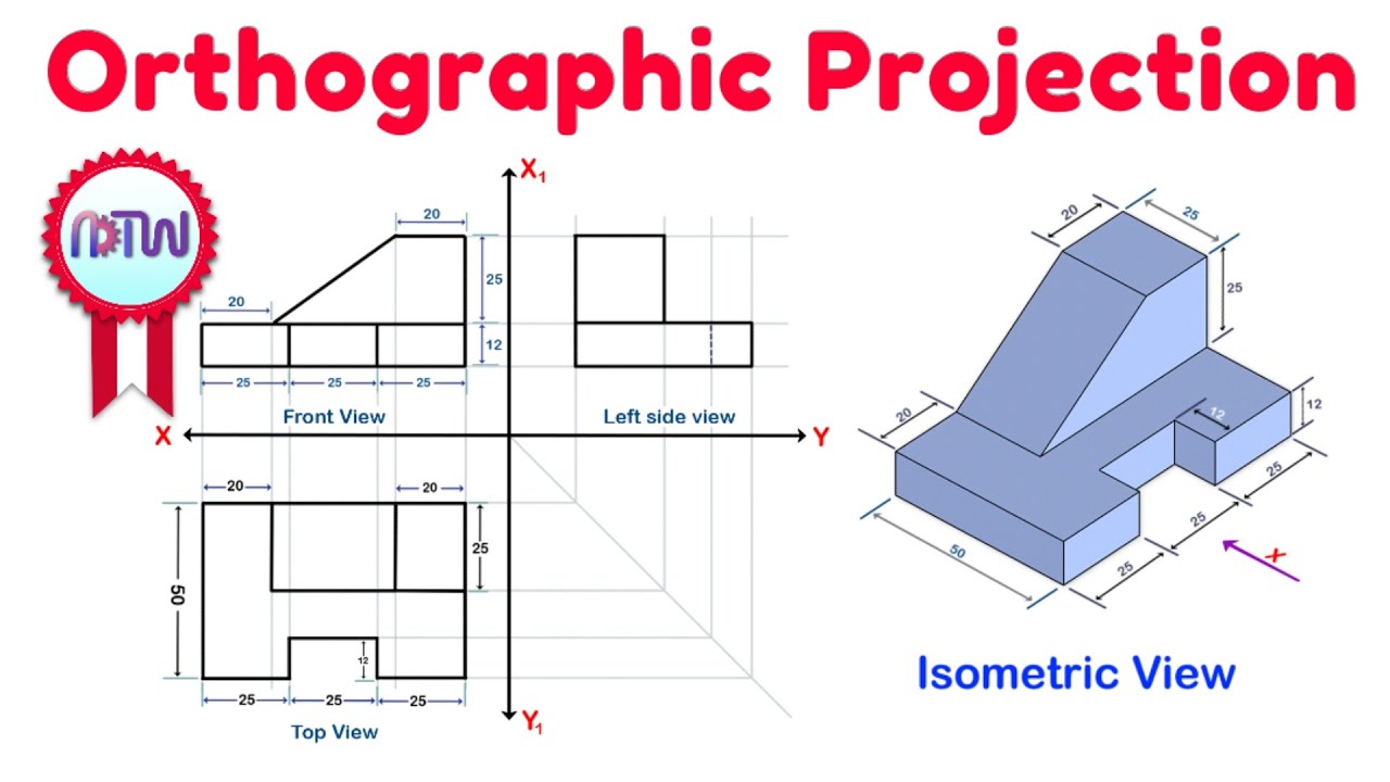
Web several types of graphical projection compared various projections and how they are produced isometric view of the object shown in the engineering drawing below. Web types of views used in drawings. The two main types of views (or “projections”) used in drawings are: Dimensions and types of dimensioning systems. This is even truer for engineers and machinists.
Orthographic Projection from isometric view in Engineering drawing
Web several types of graphical projection compared various projections and how they are produced isometric view of the object shown in the engineering drawing below. Web the front view of the cube, therefore, represents its isometric projection. The height dimension is common to the front and side views. More than one view of an object is drawn to represent it.

ORTHOGRAPHIC PROJECTION IN ENGINEERING DRAWING FUNDAMENTAL YouTube
Web understanding the types, principles, and significance of engineering drawing views empowers engineers and designers to communicate design intent effectively, visualize complex geometries accurately, and ensure manufacturability and compliance with industry standards. Web the figure formed by the projection of all the visible and invisible faces of both the interior and exterior of an object is called a “view” in.
ORTHOGRAPHIC PROJECTION IN ENGINEERING DRAWING YouTube
The 1st angle projection system is popular in european countries, whereas 3rd angle projection is popular in north america and asian countries. In most cases, a single view is not sufficient to show all necessary features, and several views are. Web section views are used extensively to show features of an object or an assembly that are not easily visible.
Web The Projection Only Shows Edges And Boundaries.
This is even truer for engineers and machinists. Edges or boundaries which are obscured (not visible from the chosen viewing direction) are shown with dashed lines. Web first angle and third angle projection are the types of orthographic projection systems to draw engineering drawings. Web the main elements of the section view are:
It Controls The Scale, Orientation, And Location Of The Views Projected From It.
Web the two main types of views (or “projections”) used in drawings are: There are three types of pictorial views: The 1st angle projection system is popular in european countries, whereas 3rd angle projection is popular in north america and asian countries. The orthographic and/or isometric views in the drawing are created from the base view.
A Point, Line, Plane, Solid, Machine Component, Or Building May Be The Object.
Web section views are used extensively to show features of an object or an assembly that are not easily visible from the exterior. Whether you're a seasoned engineer or just starting your journey, this. In both projection types, views are the same, but the position of the views with respect to each other differs. This will allow you to communicate the intent of your design for cnc machined parts.
Section Line, Section Reference Arrow, Section Reference Letters, Hatch.
Web a base view is the first view created on the drawing sheet. Visible edges or boundaries (including the extent of curved surfaces) are shown as solid lines. Dimensions and types of dimensioning systems. Isometric projection | concept and objective problems | engineering drawing | ese prelims |.