Engineering Drawing Scale
Engineering Drawing Scale - Web technical drawings are drawn to scale so that engineers, architects and builders can create the objects in the drawing to exact specifications. Most cad systems allow the drafter to draw at whatever scale he or she feels like. Web standard us engineering drawing sizes according ansi/asme y14.1 decimal inch drawing sheet size and formats below: Web an engineering scale is basically an advanced ruler designed for determining linear measurements in technical drawings. Dm, cm & mm, or yard, foot & inch. 1/4 or 1/8 (imperial units, us) scales. Web how to read an engineers scale (mostly used for roads and topographical measurements) engineer scales, such as 1˝ = 10´ or 1˝ = 50´ how to read a metric scale (mostly used for buildings in other parts of the world) how to determine the scale of a drawing where the scale isn’t indicated. On one hand, it is a general principle of engineering drawings that they are projected using standardized, mathematically certain projection methods and rules. Web there are standard scales that are being used on drawings. 1 = 20' multiply the feet by 12.
Dm, cm & mm, or yard, foot & inch. Web an engineering scale is basically an advanced ruler designed for determining linear measurements in technical drawings. Web there are standard scales that are being used on drawings. A scale is the ratio of the linear dimension of an object’s element as shown in a drawing to the actual dimensions of the same object’s element. The number on the right is the actual size. Web what is scale in engineering drawing? Web how to read an engineers scale (mostly used for roads and topographical measurements) engineer scales, such as 1˝ = 10´ or 1˝ = 50´ how to read a metric scale (mostly used for buildings in other parts of the world) how to determine the scale of a drawing where the scale isn’t indicated. If a drawing has details drawn larger than full size, it should, where practicable, include an undimensioned view of the same details drawn to actual size. However, if fabrication shops are going to be using your drawings you will help them far more by drawing views to commonly accepted engineering and architectural scales. Blueprint drawings are typically drawn in.
Web the gsfc engineering drawing standards manual is the official source for the requirements and interpretations to be used in the development and presentation of engineering drawings and related documentation for the gsfc. Web there are standard scales that are being used on drawings. • diagonal scales are used to measure distances in a unit and its immediate two subdivisions; The recommended scales for use on technical drawings are given in table. Popular internal searches in the engineering toolbox. When reading scales, the number on the left equals the measurement on the drawing; Blueprint drawings are typically drawn in. 1 for enlarged scales, scale 1: 1 = 20' multiply the feet by 12. The number on the right is the actual size.

12" ARCHITECTS SCALE RULER ALL SCALES ART DRAWING DRAFTING ENGINEERING
Prints drawn to scale allow the figures to be rendered accurately and precisely. The trick is to use the scale factor, which appears in our cad scale factors article. 38k views 3 years ago indian institute of technology delhi. One of the best ways to communicate one’s ideas is through some form of picture or drawing. Be sure to check.

PREMIUM 12 inch Triangular Engineer Scale Ruler Anodized Solid Aluminum
If a drawing has details drawn larger than full size, it should, where practicable, include an undimensioned view of the same details drawn to actual size. 38k views 3 years ago indian institute of technology delhi. Web standard us engineering drawing sizes according ansi/asme y14.1 decimal inch drawing sheet size and formats below: A scale is the ratio of the.
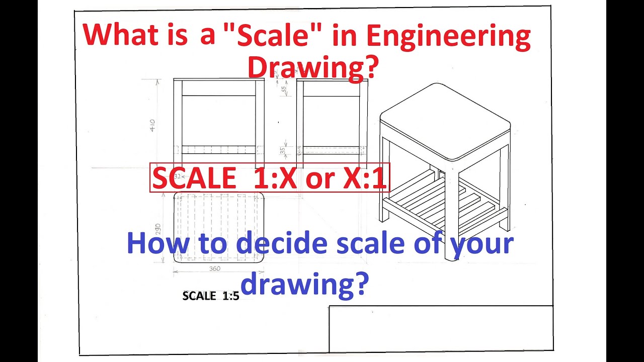
1.8What is a "Scale" in Engineering Drawing? How to decide scale of
Web standard us engineering drawing sizes according ansi/asme y14.1 decimal inch drawing sheet size and formats below: The designation of the scale used on the drawing should be shown in the title block. A beginner's look at how to read and use an engineer's scale. Web technical drawings are drawn to scale so that engineers, architects and builders can create.

How To Make A Scale Drawing in Engineering. YouTube
This video explains the meaning and importance of drawing scale in engineering drawing. Or, a scale is a measuring device that is used to determine a person’s weight. 1 for full size, scale ×: We will treat “sketching” and “drawing” as one. 1/4 or 1/8 (imperial units, us) scales.

Understanding Scales and Scale Drawings A Guide
Web there are standard scales that are being used on drawings. Web • through diagonal scale, measurements can be up to second decimal (e.g. Instead, instruments called scales are employed. 1 = 20' multiply the feet by 12. The scale factor is used to compare the scales to each other.

What is a Scale of a drawing Theory of Scales in Engineering Drawing
The scale factor is used to compare the scales to each other. A beginner's look at how to read and use an engineer's scale. Web • through diagonal scale, measurements can be up to second decimal (e.g. Web technical drawings are drawn to scale so that engineers, architects and builders can create the objects in the drawing to exact specifications..
Mechanical Drawing Scales Tutorial Engineering Drawing Basics
This is especially true for the engineer. One of the best ways to communicate one’s ideas is through some form of picture or drawing. All drawings can be classified as either drawings with scale or those not drawn to scale. Web scale in engineering drawings refers to the proportional representation of an object concerning its actual size. The purpose of.

Engineering Drawing Scale Chart
It is a very common tool used for measuring things in land development and site construction plans. Web engineering working drawings basics page 8 of 22 parallel to the object surface. • diagonal scale can measure more accurately than the plain scale. This is especially true for the engineer. Dm, cm & mm, or yard, foot & inch.
"types of scale in engineering drawing" "standard engineering drawing
In this post we will be exploring architectural scales and scale drawings. What is a scale and what are. When creating a new drawing, a suitable scale should be selected. Web there are standard scales that are being used on drawings. Most cad systems allow the drafter to draw at whatever scale he or she feels like.

plain scale in engineering drawing scales in engineering drawing
One of the best ways to communicate one’s ideas is through some form of picture or drawing. This video explains the meaning and importance of drawing scale in engineering drawing. Instead, instruments called scales are employed. Web what is scale in engineering drawing? Scales are precision instruments with fine graduations or marks.
One Of The Best Ways To Communicate One’s Ideas Is Through Some Form Of Picture Or Drawing.
Web to convert an engineering drawing scale to a scale factor: Web changing from one scale to another seems like a complex task, especially if you need to convert from an architectural scale to an engineering scale. The number on the right is the actual size. Web standard us engineering drawing sizes according ansi/asme y14.1 decimal inch drawing sheet size and formats below:
Prints Drawn To Scale Allow The Figures To Be Rendered Accurately And Precisely.
What is a scale and what are. We will treat “sketching” and “drawing” as one. 1/4 or 1/8 (imperial units, us) scales. Most cad systems allow the drafter to draw at whatever scale he or she feels like.
All Drawings Can Be Classified As Either Drawings With Scale Or Those Not Drawn To Scale.
Dm, cm & mm, or yard, foot & inch. Web an engineering scale is basically an advanced ruler designed for determining linear measurements in technical drawings. “sketching” generally means freehand drawing. On one hand, it is a general principle of engineering drawings that they are projected using standardized, mathematically certain projection methods and rules.
The Purpose Of This Guide Is To Give You The Basics Of Engineering Sketching And Drawing.
Or, a scale is a measuring device that is used to determine a person’s weight. Web there are standard scales that are being used on drawings. Web engineering working drawings basics page 8 of 22 parallel to the object surface. The scales are the ratio of the linear dimension of an element of an object as represented in the original drawing to the actual linear dimension of the same element of the object itself.