Engineering Drawing Symbols List
Engineering Drawing Symbols List - Web this section standardizes the symbols for specifying geometrical characteristics and other dimensional requirements on engineering drawings. The following tables show how to construct the symbols. Engineering drawing abbreviations and symbols are used to communicate and detail the characteristics of an engineering drawing. 1.5 list the five drawing categories used on engineering. Symbols or conventions used on the drawing and any additional information the designeror draftsmanfeltwas necessaryto understandthedrawing. 10 a, but ‘a few amperes’). Zoning, a drawing may be divided up into a grid using letters and numbers. The following is a short list of symbols that normally appear on a technical drawing and need understanding. Here are more commonly used engineering drawing symbols and design elements as below. Many additional symbols are listed and described in this section, including symbols for datums, modifiers,.
The mechanical engineering branch, mechanical systems division, has been delegated This video is based on the syllabus of engineering drawing ii. This question is asked for 5 marks which is very easy to get marks in ioe. Geometric tolerances are specified using symbols on a drawing. Web engineering drawings (aka blueprints, prints, drawings, mechanical drawings) are a rich and specific outline that shows all the information and requirements needed to manufacture an item or product. Many additional symbols are listed and described in this section, including symbols for datums, modifiers,. It is used to indicate how. The table below shows symbols for the geometrical characteristics. To read and understand engineering fluid diagrams and prints, usually referred to as p&ids, an individual must be familiar with the basic symbols. Zoning is usually used for large size drawing sheets where it allows easy references to various parts of the drawing
It is more than simply a drawing, it is a graphical language that communicates ideas and information. Web this section standardizes the symbols for specifying geometrical characteristics and other dimensional requirements on engineering drawings. Architect's scale and engineer's scale; Web geometric dimensioning and tolerancing symbols you can either create your own library of gd&t symbols, or use one of autocad’s gd&t fonts to insert the symbols as text. Geometric tolerances are specified using symbols on a drawing. 1.5 list the five drawing categories used on engineering. We offer you our tips which we believe are useful for dispelling uncertainty by comparing the symbol with its graphic representation. Web any engineering drawing should show everything: Here are more commonly used engineering drawing symbols and design elements as below. Our collection of common p&id symbols will help you better understand the piping & instrumentation diagrams on any engineering project.

ANSI Standard JSTD710 Architectural Drawing Symbols Bedrock Learning
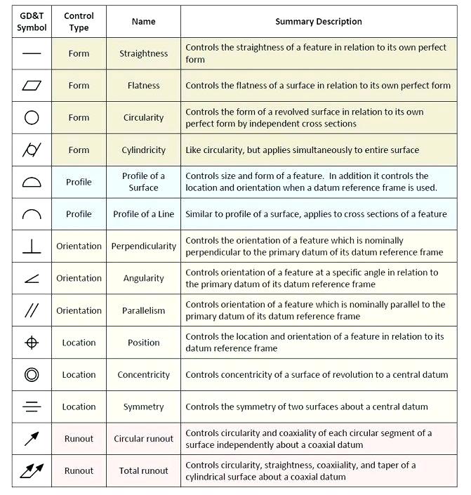
Classification and symbols of geometric tolerance characteristics. Any needed height h 2 h h 2 h 60° 2 h identification letter datum feature symbol datum target symbol target point and. Web geometric dimensioning and tolerancing symbols you can either create your own library of gd&t symbols, or use one of autocad’s gd&t fonts to insert the symbols as text. Web.
Engineering Symbols Chart A Visual Reference of Charts Chart Master
The following is a short list of symbols that normally appear on a technical drawing and need understanding. 1.5 list the five drawing categories used on engineering. Geometric tolerances are specified using symbols on a drawing. Eo 1.1 identify the symbols used on engineering p&ids for the following types of valves: To read and understand engineering fluid diagrams and prints,.

Civil Engineering Drawing Symbols And Their Meanings at PaintingValley
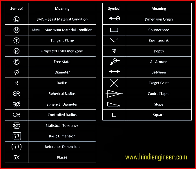
Web engineering drawing abbreviations and symbols are used to communicate and detail the characteristics of an engineering drawing. The charts below are a complete list of abbreviations and symbols in engineering drawings. Currently, we have 16 symbols for geometric tolerances, which are categorized according to the tolerance they specify. To read and understand engineering fluid diagrams and prints, usually referred.

Mechanical Engineering Drawing Symbols Pdf Free Download at
The following is a short list of symbols that normally appear on a technical drawing and need understanding. Web this list includes abbreviations common to the vocabulary of people who work with engineering drawings in the manufacture and inspection of parts and assemblies. This question is asked for 5 marks which is very easy to get marks in ioe. 2.7k.

Engineering Drawing Symbols List Chart Explain Mechanical Drawing
It is used to indicate how. Web engineering drawings arethe indus try's means of communicating detailed and accurate information on how to fabricate, assemble, troubles hoot, repair, and operate. Web a convenient guide for geometric dimensioning and tolerancing (gd&t) symbols at your fingertips. Web when the parts list is very large a separate drawing sheet may be used for the.

Engineering Drawing Symbols And Their Meanings Pdf at PaintingValley
Web 1.2 state how the grid system on an engineering drawing is used to locate a piece of equipment. Web engineering fluids diagrams and prints. Web engineering drawings (aka blueprints, prints, drawings, mechanical drawings) are a rich and specific outline that shows all the information and requirements needed to manufacture an item or product. One can pack a great deal.

Engineering Drawing Symbols And Their Meanings Pdf at PaintingValley
A complete understanding of the object should be possible from the drawing. Eo 1.1 identify the symbols used on engineering p&ids for the following types of valves: 1.3 state the three types of information provided in the revision block of an engineering drawing. Click on the links below to learn more about each gd&t symbol or concept, and be sure.

Engineering Drawing Symbols And Their Meanings Pdf at GetDrawings
1.5 list the five drawing categories used on engineering. 1.3 state the three types of information provided in the revision block of an engineering drawing. Classification and symbols of geometric tolerance characteristics. The mechanical engineering branch, mechanical systems division, has been delegated Web this list includes abbreviations common to the vocabulary of people who work with engineering drawings in the.
Mechanical Engineering Drawing Symbols Pdf Free Download at
Web find common gd&t symbols in convenient charts broken down by their use in drawing and drafting. Web it includes a set of symbols, text, and tolerances that provide precise information about the size, shape, and orientation of parts and assemblies. The mechanical engineering branch, mechanical systems division, has been delegated Currently, we have 16 symbols for geometric tolerances, which.

Standard Engineering Drawing Symbols Design Talk
A complete understanding of the object should be possible from the drawing. 10 a, but ‘a few amperes’). Geometric tolerances are specified using symbols on a drawing. If the isometric drawing can show all details and all dimensions on one drawing, it is ideal. Web when the parts list is very large a separate drawing sheet may be used for.
Zoning, A Drawing May Be Divided Up Into A Grid Using Letters And Numbers.
1.4 state the purpose of the notes and legend section of an engineering drawing. It is more than simply a drawing, it is a graphical language that communicates ideas and information. Classification and symbols of geometric tolerance characteristics. Symbols or conventions used on the drawing and any additional information the designeror draftsmanfeltwas necessaryto understandthedrawing.
2.7K Views 1 Year Ago Kathmandu.
Specification (technical standard) structural drawing Web engineering drawing abbreviations and symbols are used to communicate and detail the characteristics of an engineering drawing. To read and understand engineering fluid diagrams and prints, usually referred to as p&ids, an individual must be familiar with the basic symbols. Web when the parts list is very large a separate drawing sheet may be used for the parts list alone.
Our Collection Of Common P&Id Symbols Will Help You Better Understand The Piping & Instrumentation Diagrams On Any Engineering Project.
Need to know for dispelling uncertainty in drawings. The flatness symbol is represented by a straight line with a circle at the end. A complete understanding of the object should be possible from the drawing. Web engineering fluids diagrams and prints.
Many Additional Symbols Are Listed And Described In This Section, Including Symbols For Datums, Modifiers,.
Our process flow diagram symbols list will help you better understand the pfd symbology on any engineering project. However, if the object in figure 2 had a hole on the back. Web any engineering drawing should show everything: This question is asked for 5 marks which is very easy to get marks in ioe.