Gdt Drawing Examples
Gdt Drawing Examples - It is an important tool for ensuring the interchangeability, functional accuracy, and reliability of manufactured components. This course will teach you the basics of how to understand gd&t symbols and their use. Web common gd&t symbols are listed in the table below. It is documented in asme y14.5m which has the symbols, rules, and simple examples. Web this page explains the 16 symbols used in gd&t, and the classification thereof. Gd&t drawing isn't just about making things look good on paper; “learning gd&t from scratch,” provided by keyence, walks you through the basics of geometric dimensioning and tolerancing, datums, and measurements by coordinate measuring. The datum reference frame (drf) interpreting gd&t symbols. Web geometric dimensioning and tolerancing (gd&t) is a system of symbols and standards used in engineering drawings and models to specify the required form, size, orientation, and location of parts and features. Let’s learn more about gd&t symbols with.
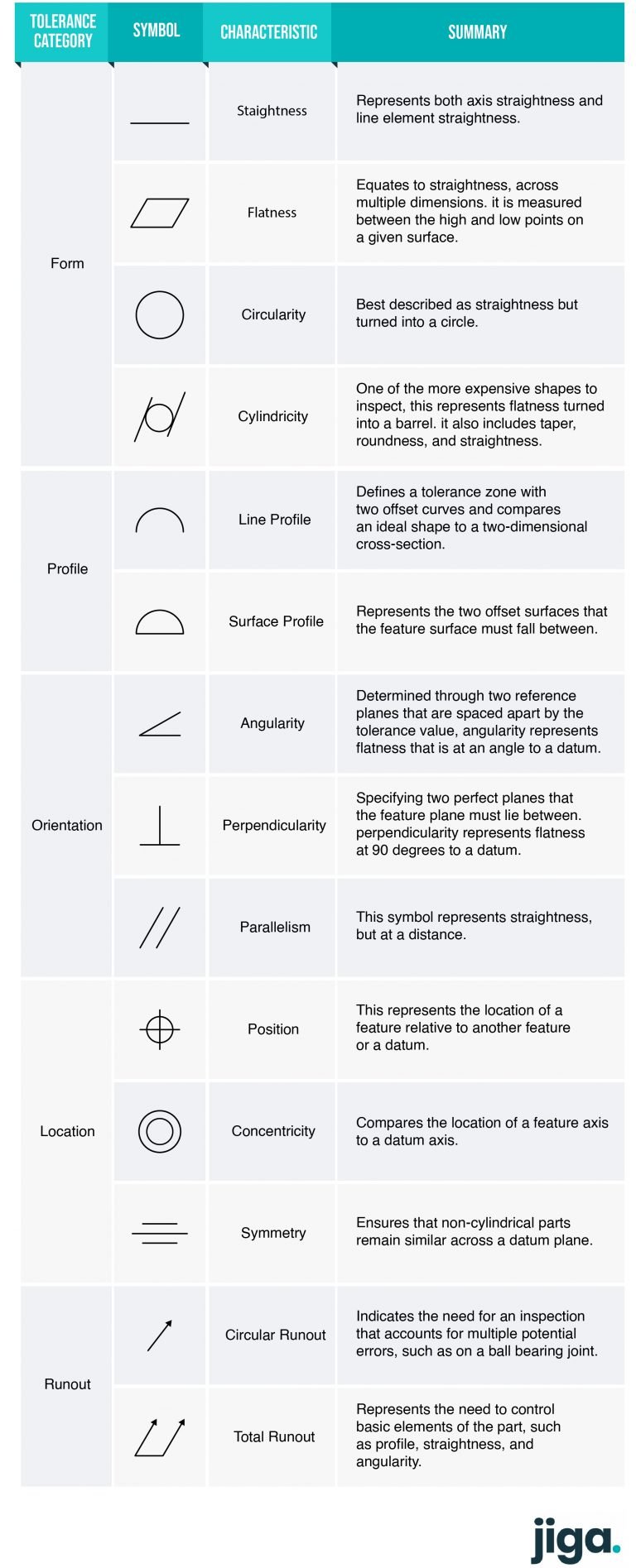
Currently, we have 16 symbols for geometric tolerances, which are categorised according to the tolerance they specify. Examples on how to interpret gd&t: This video shows how to select datum features. Web gd&t is a particular set of conventions used on engineering drawings (often called “prints” from the older “blueprints”) that communicate how parts should fit together and how they function. Let’s take a look at an example of when to use a local coordinate system: Classification and symbols of geometric tolerance characteristics. The intent of the design of a mirror is for it to be flat to prevent a distorted reflection. In this drawing, there are four screw holes near the center of the part that don’t interface with any of the other features. Limitations of tolerancing before gd&t. This course will teach you the basics of how to understand gd&t symbols and their use.
The asme y14.5 standard establishes symbols, definitions, and rules for geometric dimensioning and tolerancing. A part drawing may include a single gd&t callout, or the drawing may be fully defined using gd&t depending on part requirements. Using coordinate dimensioning and tolerancing, you could try to avoid a wavy surface by adding a tight thickness tolerance to the drawing. “learning gd&t from scratch,” provided by keyence, walks you through the basics of geometric dimensioning and tolerancing, datums, and measurements by coordinate measuring. Web there are 7 aspects of the gd&t methodology that we will discuss, these include: It is compilation of symbols and rules that effi ciently describe and control dimensioning & tolerancing for all drawings (castings, machined components,etc.). Also asme y14.8 has guidance for casting and forging drawings. This course will teach you the basics of how to understand gd&t symbols and their use. It is documented in asme y14.5m which has the symbols, rules, and simple examples. It's about streamlining the manufacturing process.

GD&T for beginners step by step approach to do gd&t for mechanical
Local coordinates m & n for screw holes. Datums on a drawing of a part are represented using the symbol shown below. Currently, we have 16 symbols for geometric tolerances, which are categorised according to the tolerance they specify. Review the slides use your reference material to find the errors. The intent of the design of a mirror is for.

GD&T The Beginner's Guide to Geometric Dimensioning and Tolerancing
This video shows how to select datum features. Gd&t ( geometrical dimensions and tolerances ) is the new vocabulary of engineering drawings. Let’s take a look at an example of when to use a local coordinate system: Examples on how to interpret gd&t: Using coordinate dimensioning and tolerancing, you could try to avoid a wavy surface by adding a tight.

GD&T 101 An Introduction to Geometric Dimensioning and Tolerancing
Web asme y14.5 is an established, widely used gd&t standard containing all the necessary information for a comprehensive gd&t system. Views, dimensions, tolerances, symbols, datum’s, feature control frames & title blocks. Web 2 what is gd&t? Gd&t, short for geometric dimensioning and tolerancing, is a system for defining and communicating design intent and engineering tolerances that helps engineers and manufacturers.
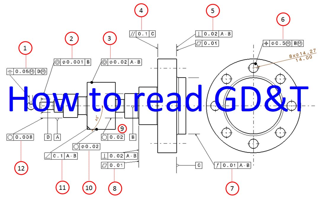
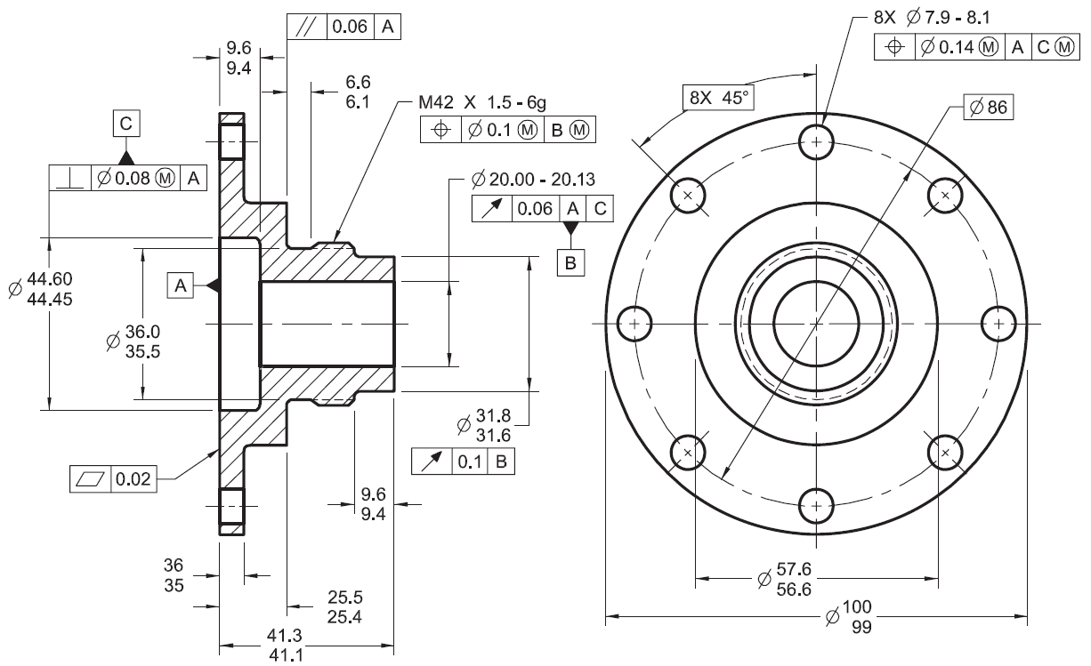
Examples on how to interpret GD&T Form, orientation, location and run
“learning gd&t from scratch,” provided by keyence, walks you through the basics of geometric dimensioning and tolerancing, datums, and measurements by coordinate measuring. Geometric dimensioning and tolerancing (gd&t) consists of a set of symbols and rules for applying them that communicates the requirements of an engineering blueprint. Examples on how to interpret gd&t: The datum reference frame (drf) interpreting gd&t.

GD&T Tips Profile As a General Tolerance
In this drawing, there are four screw holes near the center of the part that don’t interface with any of the other features. These are grouped into symbols relating to form, profile, orientation, runout and location. “learning gd&t from scratch,” provided by keyence, walks you through the basics of geometric dimensioning and tolerancing, datums, and measurements by coordinate measuring. Web.
GD&T Drawings KOHLEX
Examples on how to interpret gd&t: Web asme y14.5 is an established, widely used gd&t standard containing all the necessary information for a comprehensive gd&t system. We can create a local coordinate system just for the four holes. Web gd&t symbols and definitions help convey the designed object and allow for the manufacturing of mechanical parts in a way that.
GD&T (Geometric Dimensioning and Tolerancing) Guide Jiga
Gd&t ( geometrical dimensions and tolerances ) is the new vocabulary of engineering drawings. It is documented in asme y14.5m which has the symbols, rules, and simple examples. Let’s take a look at an example of when to use a local coordinate system: It is an important tool for ensuring the interchangeability, functional accuracy, and reliability of manufactured components. We.
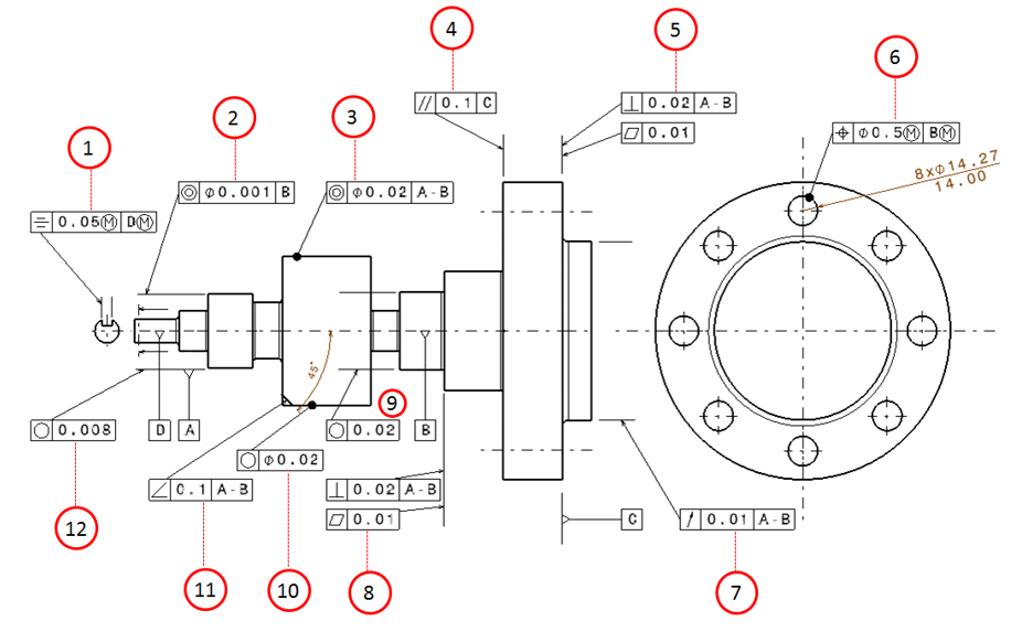
Examples on how to interpret GD&T Form, orientation, location and run
Web may 1, 2022 by brandon fowler. Web a convenient guide for geometric dimensioning and tolerancing (gd&t) symbols at your fingertips. Web 2 what is gd&t? Web download the white paper. The first tool in your engineering drawing toolbox is the drawing view.

GD&T Drawings KOHLEX
Web gd&t drawings and symbols. Limitations of tolerancing before gd&t. This video shows how to select datum features. Also asme y14.8 has guidance for casting and forging drawings. Web gd&t is a means of dimensioning & tolerancing a drawing which considers the function of the.

GD&T Basics What You Need to Know
It is compilation of symbols and rules that effi ciently describe and control dimensioning & tolerancing for all drawings (castings, machined components,etc.). It is an important tool for ensuring the interchangeability, functional accuracy, and reliability of manufactured components. The datum features are qualified with flatness. Gd&t, short for geometric dimensioning and tolerancing, is a system for defining and communicating design.
Web Geometric Dimensioning And Tolerancing, By D.
Gd&t allows for comprehensive and consistent tolerances with the use of relatively simple tools. The datum features are qualified with flatness. In this drawing, there are four screw holes near the center of the part that don’t interface with any of the other features. Web geometric dimensioning and tolerancing (gd&t) is a system of symbols and standards used in engineering drawings and models to specify the required form, size, orientation, and location of parts and features.
Views, Dimensions, Tolerances, Symbols, Datum’s, Feature Control Frames & Title Blocks.
True position theory (size value in rectangular frame) This video shows how to select datum features. Limitations of tolerancing before gd&t. Geometric dimensioning and tolerancing (gd&t) is the building block of modern engineering drawings.
This Is The Language That Your Drawings Speak.
Using coordinate dimensioning and tolerancing, you could try to avoid a wavy surface by adding a tight thickness tolerance to the drawing. The first tool in your engineering drawing toolbox is the drawing view. Gd&t ( geometrical dimensions and tolerances ) is the new vocabulary of engineering drawings. Review the slides use your reference material to find the errors.
“Learning Gd&T From Scratch,” Provided By Keyence, Walks You Through The Basics Of Geometric Dimensioning And Tolerancing, Datums, And Measurements By Coordinate Measuring.
Click on the links below to learn more about each gd&t symbol or concept, and be sure to download the free wall chart for a quick reference when at your desk or on the shop floor. Web there are 7 aspects of the gd&t methodology that we will discuss, these include: Web 2 what is gd&t? This course will teach you the basics of how to understand gd&t symbols and their use.