How To Draw A State Machine Diagram
How To Draw A State Machine Diagram - States (simple states or composite states) state transitions connecting the states. Visually capture the behavior of an object in a system using uml, a standard adopted worldwide. Using your chosen tool, draw the state diagram by representing each state as a box or circle and connecting them with arrows to indicate transitions. Draw directed lines to depict changes from one state to another. Web state diagrams have been used in programming to describe the various possible states that a system can be in for decades. Below, you can see both these elements at work in a basic diagram for student life. You should see the shapes window next to the diagram. 1) behavioral state machine diagram 2) protocol state machine diagram. Web a state machine diagram is a behavior that specifies the sequences of states an object goes through during its lifetime in response to events. The article discusses how to create a state diagram for a system, using the example of a vending machine.
State transition diagram is a useful fsm representation and design aid: Transitions are marked with arrows that flow from one state to another, showing how the states change. It shows the various states that the machine can be in and the transitions that occur when the user interacts with the. Below, you can see both these elements at work in a basic diagram for student life. Web 5 steps to draw state machine diagram. “if l=1 at the clock edge, then jump to l=1 l=1 state 01.”. Using your chosen tool, draw the state diagram by representing each state as a box or circle and connecting them with arrows to indicate transitions. 1) behavioral state machine diagram 2) protocol state machine diagram. Web a state machine diagram is a behavior that specifies the sequences of states an object goes through during its lifetime in response to events. Vp online features a powerful uml diagram tool that lets you create state machine diagram and other uml diagrams easily and quickly.
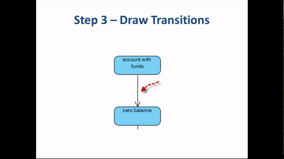
Smart shapes and connectors, shape search, and easy styling options to quickly and easily create all types of uml diagrams. In this tutorial, we will name the diagram state machine diagram tutorial. Select the uml state machine diagram. The article then presents a more detailed. Web enter the plantuml description of your state machines in the textbox, and click apply. Web design state machine diagram online. Web this video will show you how to draw a state machine diagram in 5 steps.we'll walk through an example which visually describes the behavior of a bank account. Transitions are marked with arrows that flow from one state to another, showing how the states change. Web plantuml provides a simple and intuitive syntax to create state machine diagrams. Unsynchronized level to user input d q d q l pulse p fsm.
UML State Machine Diagram Tutorial Software Ideas Modeler
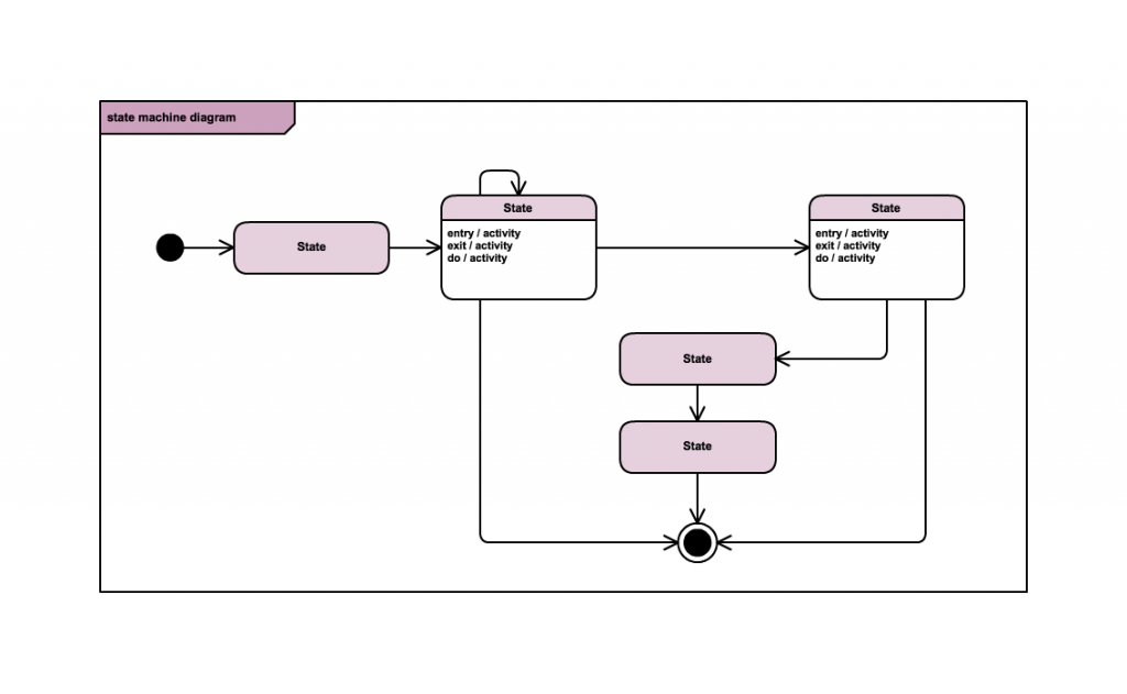
Use rectangles for states, arrows for transitions, and circles or rounded rectangles for initial and final states. After signing up, open a blank document and enable the uml shape libraries. A state machine are used to specify the behavior of objects that must respond to asynchronous stimulus or whose current behavior depends on their past. Web a state of an.

MSP430 State Machine project with LCD and 4 user buttons
Select diagram > new from the tool bar. Select the uml state machine diagram. Draw the diagram with appropriate notations. After that, click the “new flowchart” button from the landing page and the editing panel will appear. Or if you have a file open already, click file > new.
Blog Draw a UML state machine diagram
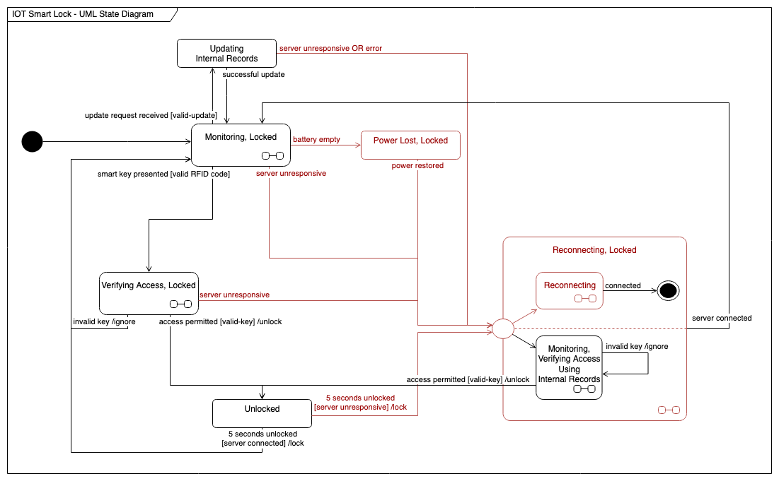
The change in one state to another is due to the occurrence of some event. In conclusion, drawing a state diagram is a valuable skill for system. The article discusses how to create a state diagram for a system, using the example of a vending machine. In the dialog box, select the either metric units or us units. Be sure.
Event driven state machine 101 Adaptive Financial Consulting
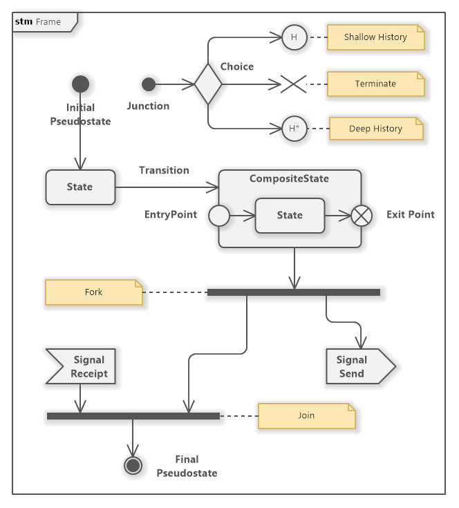
A state machine diagram is a graph consisting of: The initial state diagram presented is a simple version that shows the primary states and transitions involved in the vending machine’s behavior. Draw directed lines to depict changes from one state to another. States (simple states or composite states) state transitions connecting the states. Web a state is a constraint or.
A simple guide to drawing your first state diagram (with examples) Cacoo
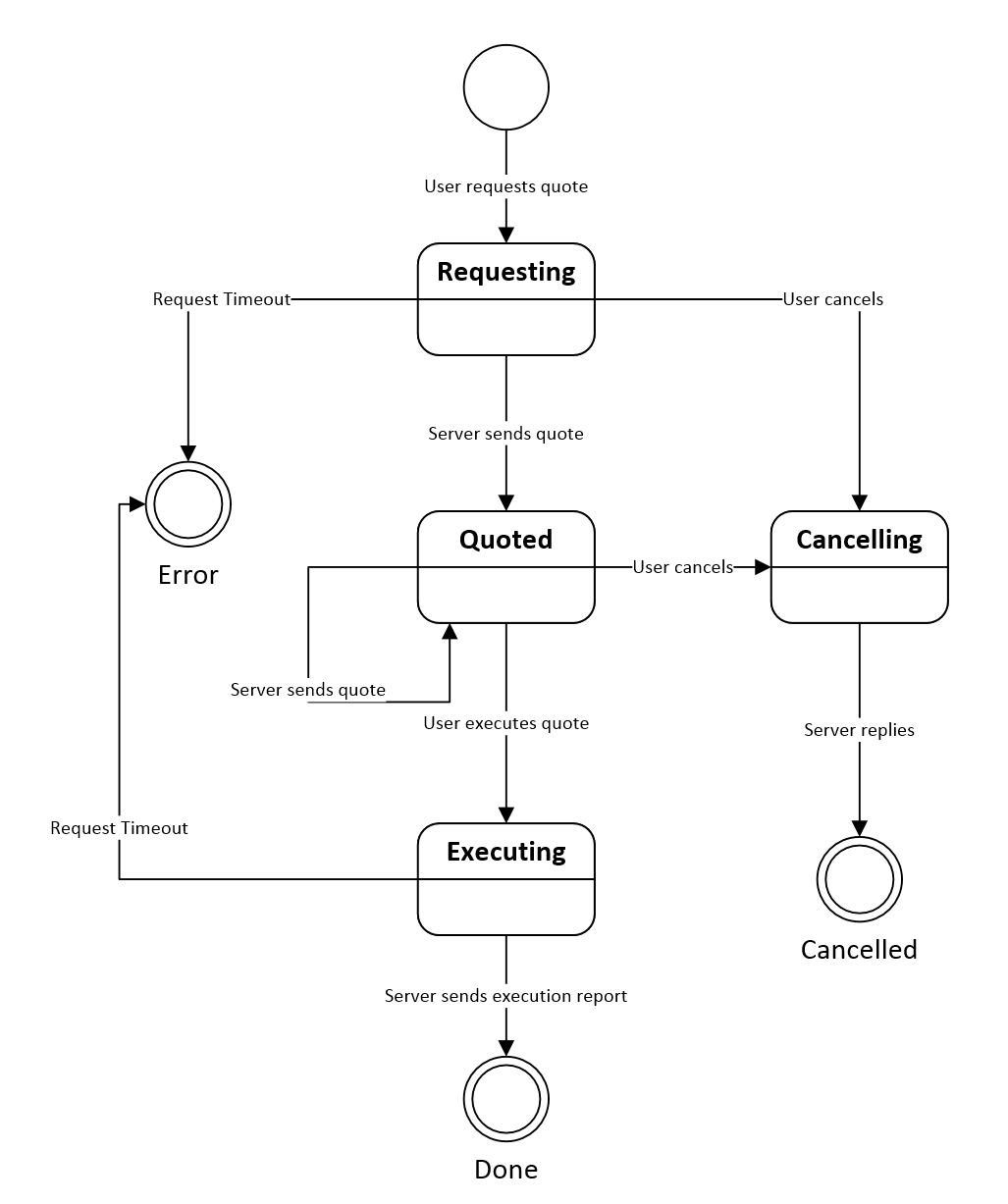
This state diagram models the behavior of a vending machine that dispenses candy bars and gives change if the user inserts excess amount. Visually capture the behavior of an object in a system using uml, a standard adopted worldwide. In conclusion, drawing a state diagram is a valuable skill for system. All of the possible states of a particular component.

compiler construction Drawing Finite State Machine FSM for finding
Uml state machine diagram (or some. Clarify what events kick off the transitions. These diagrams consist of states, transitions, and optional actions or events associated with each transition. A state machine diagram is a graph consisting of: Infinite canvas to draw large, complex state machine diagrams with minimal effort.
A simple guide to drawing your first state diagram (with examples) Nulab
A state machine diagram is a graph consisting of: Vp online features a powerful uml diagram tool that lets you create state machine diagram and other uml diagrams easily and quickly. You will now see an empty diagram with. The article then presents a more detailed. Now, take all this information and draw it out.

State Machine Diagram Tutorial Lucidchart
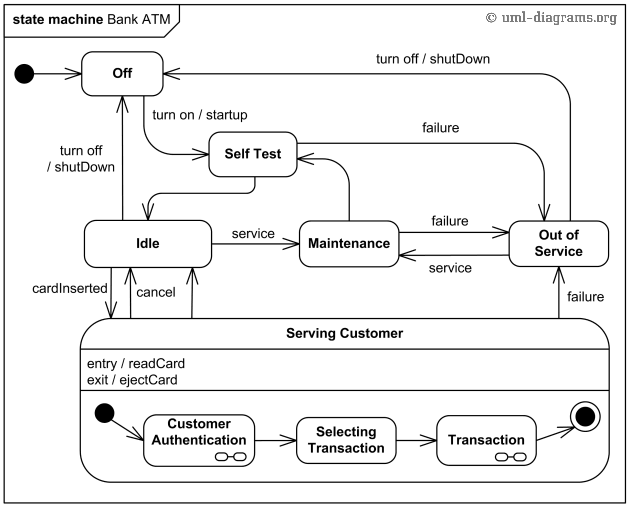
Web creating a state machine diagram. Now, take all this information and draw it out. Behavioral diagram and it represents the behavior using finite state transitions. Vp online features a powerful uml diagram tool that lets you create state machine diagram and other uml diagrams easily and quickly. A state machines are used to model the behavior of.
State Machine Diagram Tutorial
Repeat the process until you complete. Be sure to connect everything in a way that makes sense. Web creating a state machine diagram. The initial state diagram presented is a simple version that shows the primary states and transitions involved in the vending machine’s behavior. Name the diagram, then click ok.
5 Steps to Draw a State Machine Diagram YouTube
Web to create your own state machine diagrams, sign up for a free lucidchart account. Use rectangles for states, arrows for transitions, and circles or rounded rectangles for initial and final states. Transitions are marked with arrows that flow from one state to another, showing how the states change. All of the possible states of a particular component must be.
Web A State Diagram Is Used To Represent The Condition Of The System Or Part Of The System At Finite Instances Of Time.
States are represented with rectangles with rounded corners that are labeled with the name of the state. Web this video will show you how to draw a state machine diagram in 5 steps.we'll walk through an example which visually describes the behavior of a bank account. You can use the search bar above to filter results. Smart shapes and connectors, shape search, and easy styling options to quickly and easily create all types of uml diagrams.
You Should See The Shapes Window Next To The Diagram.
You will now see an empty diagram with. The initial state diagram presented is a simple version that shows the primary states and transitions involved in the vending machine’s behavior. States (simple states or composite states) state transitions connecting the states. Repeat the process until you complete.
Clarify How Different Events Drive Transitions Between States.
You can construct your diagrams with drag and drop, save your work in cloud workspace, output and share your design via numerous formats such as png, jpg, svg, pdf, etc. L=1 binary values of states. A state machines are used to model the behavior of. Using your chosen tool, draw the state diagram by representing each state as a box or circle and connecting them with arrows to indicate transitions.
A State Machine Are Used To Specify The Behavior Of Objects That Must Respond To Asynchronous Stimulus Or Whose Current Behavior Depends On Their Past.
There is a total of two types of state machine diagrams: They also quickly show which states lead to each other, and what triggers a change of state. Use rectangles for states, arrows for transitions, and circles or rounded rectangles for initial and final states. After that, click the “new flowchart” button from the landing page and the editing panel will appear.