How To Draw Bode Diagram
How To Draw Bode Diagram - What is the frequency domain response? How are the piecewise linear. Following the discussion above, the way to make a bode diagram is to split the function up into its constituent parts, plot the magnitude and. Web draw the bode plot from a transfer function using the bode plot generator. Web we draw its intersection with the frequency axis where ω = ωc, since that’s where the magnitude is 0 db. Web bode(sys) creates a bode plot of the frequency response of a dynamic system model sys. Firstly, write the given transfer function in the time constant form. A time delay of 0.01 seconds (magnitude and phase of time delay described here ). The plot displays the magnitude (in db) and phase (in degrees) of the system response. Web making a bode diagram.
Web bode(sys) creates a bode plot of the frequency response of a dynamic system model sys. The plot displays the magnitude (in db) and phase (in degrees) of the system response. Web how to generate a bode plot with ltspice. To interactively shape the open. Connect with straight line from ω = ω0. To draw bode diagram there are four steps: Next, identify the factors like k, poles and zeros at the. In other words, what does a bode plot represent? this includes an animation. Firstly, write the given transfer function in the time constant form. Web we draw its intersection with the frequency axis where ω = ωc, since that’s where the magnitude is 0 db.
Web we draw its intersection with the frequency axis where ω = ωc, since that’s where the magnitude is 0 db. For the development of dynamic systems in electrical engineering, control. Find the poles and zeros. Connect with straight line from ω = ω0. Rewrite the transfer function in proper form. A bode plot is a graphical representation that shows how the gain (magnitude) and phase of a system respond. Firstly, write the given transfer function in the time constant form. Web get the map of control theory: | drawing bode plots has never been so easy. Separate the transfer function into its constituent parts.
A Beginner's Guide to Bode Plots
Next, identify the factors like k, poles and zeros at the. To interactively shape the open. A time delay of 0.01 seconds (magnitude and phase of time delay described here ). Write the transfer function of the circuit in the form. Web the bode magnitude plot is a graph of the absolute value of the gain of a circuit, as.

Some features of the Bode plot of a complex lead compensator. The Bode
Write the transfer function of the circuit in the form. Draw the bode diagram for each part. Detailed instructions on how to draw a bode plot diagram on first order denominators and integrators. What is the frequency domain response? Rewrite the transfer function in proper form.

ME 340 Example Drawing Bode Plot of a Transfer Function 2 YouTube
Separate the transfer function into its constituent parts. Web the steps to sketch the bode plot are as follows: To interactively shape the open. Web how to generate a bode plot with ltspice. Web technique to get started:

Bode Plot EXAMPLE YouTube
Web making a bode diagram. Web the steps to sketch the bode plot are as follows: This is done in the. Web get the map of control theory: Web how to generate a bode plot with ltspice.

how to draw bode plot in MATLAB Bode plot using MATLAB MATLAB
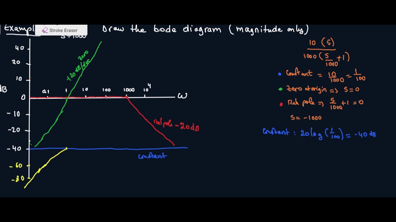
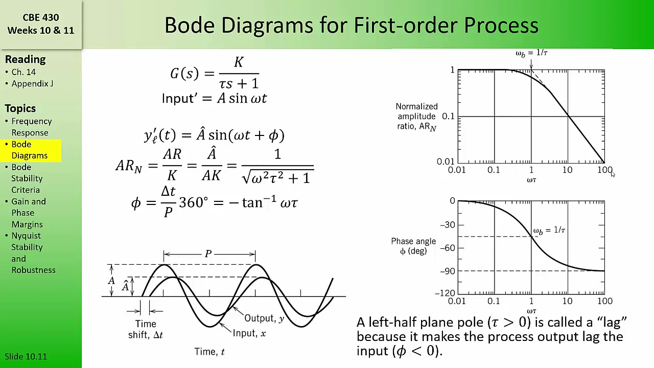
Write the transfer function of the circuit in the form. Draw the bode diagram for each part. Identify individual terms and convert transfer function to standard form. H(jw) 1 w j + 1 1 + j w z2 = a(w) + p1. In other words, what does a bode plot represent? this includes an animation.

Bode Plot Example Bode Diagram Example MATLAB Electrical Academia
The gain is plotted in decibels, while frequency is shown on a. Separate the transfer function into its constituent parts. Find the poles and zeros. Draw the bode diagram for each part. What is the frequency domain response?
How to Draw a Bode Plot (Part 2) YouTube
Web we draw its intersection with the frequency axis where ω = ωc, since that’s where the magnitude is 0 db. What is the frequency domain response? Web bode(sys) creates a bode plot of the frequency response of a dynamic system model sys. Rewrite the transfer function in proper form. Web the bode diagram of an electronic circuit consists of.

simple method to draw bode plot3 YouTube
Detailed instructions on how to draw a bode plot diagram on first order denominators and integrators. This is done in the. Write the transfer function of the circuit in the form. Draw the bode diagram for each part. In other words, what does a bode plot represent? this includes an animation.

Bode Plot Example Bode Diagram Example MATLAB Electrical Academia
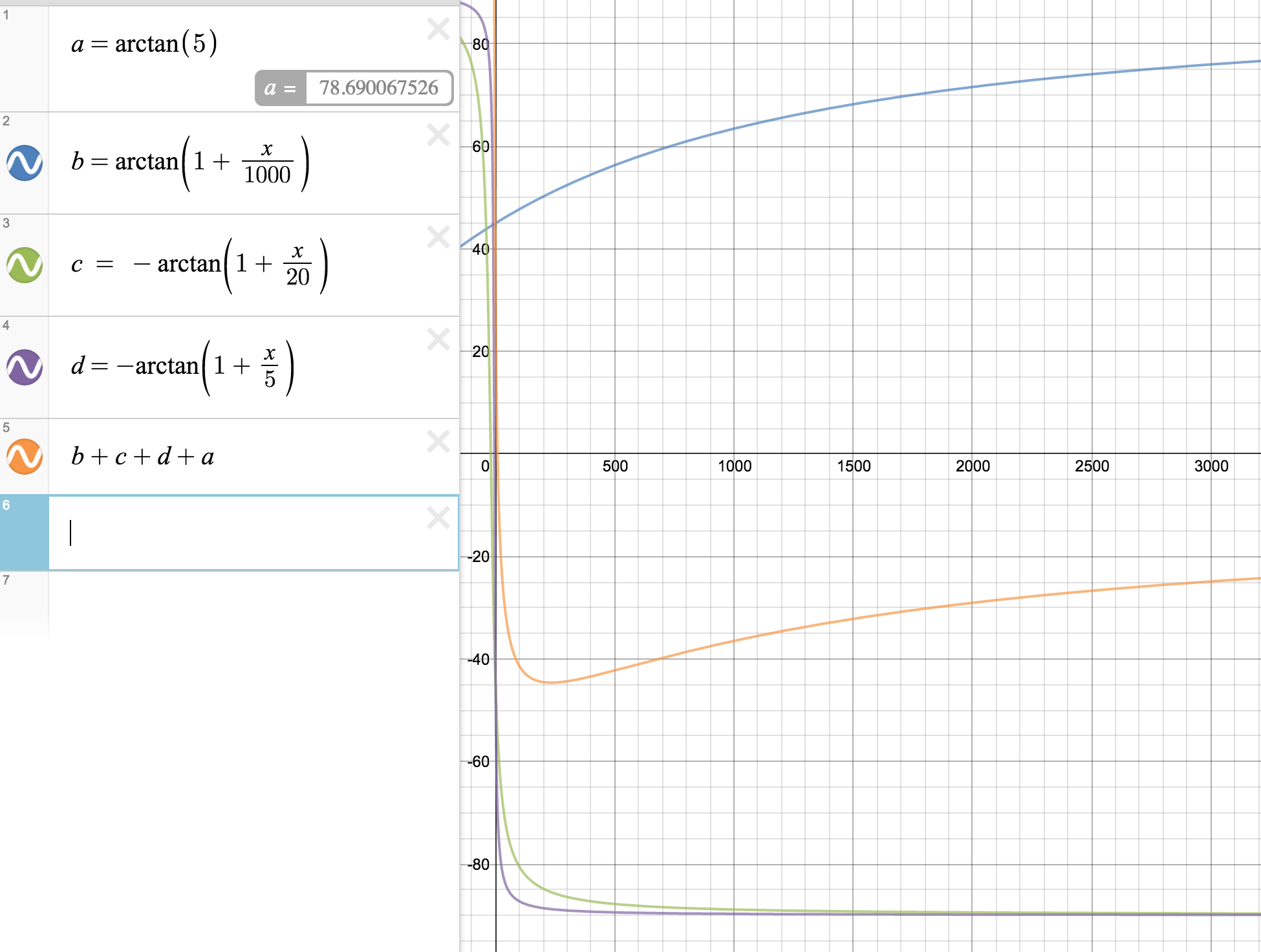
What is the frequency domain response? For the development of dynamic systems in electrical engineering, control. This is done in the. −40 −20 0 20 40 magnitude (db) 103 104 105 106 107 ω (rad/s). Web draw the bode plot from a transfer function using the bode plot generator.
CBE 430 Week 10 04 Bode diagrams part 1 YouTube
Next, identify the factors like k, poles and zeros at the. Draw the bode diagram for each part. Draw the bode diagram for each part. How are the piecewise linear. Web how to generate a bode plot with ltspice.
| Drawing Bode Plots Has Never Been So Easy.
Web get the map of control theory: Web how to generate a bode plot with ltspice. To interactively shape the open. 81k views 8 years ago.
A Time Delay Of 0.01 Seconds (Magnitude And Phase Of Time Delay Described Here ).
Web bode(sys) creates a bode plot of the frequency response of a dynamic system model sys. Web the steps to sketch the bode plot are as follows: Write the transfer function of the circuit in the form. Web technique to get started:
Draw The Overall Bode Diagram By Adding Up The Results From Part 3.
To draw bode diagram there are four steps: Detailed instructions on how to draw a bode plot diagram on first order denominators and integrators. Web making a bode diagram. Web the bode diagram of an electronic circuit consists of two graphs that plot respectively the gain gdb and the phase difference as a function of the frequency in logarithmic scale.
In Other Words, What Does A Bode Plot Represent? This Includes An Animation.
This is done in the. Web the bode magnitude plot is a graph of the absolute value of the gain of a circuit, as a function of frequency. Connect with straight line from ω = ω0. Following the discussion above, the way to make a bode diagram is to split the function up into its constituent parts, plot the magnitude and.