How To Draw Bode Plot From Transfer Function
How To Draw Bode Plot From Transfer Function - Next, identify the factors like k, poles and zeros at the origin, etc. Inspection of t(s) in normalized form to: Click on the transfer function in the table below to jump to that example. Refer to the following table. 40 db/decade at the frequency of the zero or pole. For the transfer function given, sketch the bode log magnitude diagram which shows how the log magnitude of the system is affected by changing input frequency. Dividing the transfer function denominator and numerator by 0.001 places it into standard form. Several examples of the construction of bode plots are included here; Rewrite the transfer function in proper form. (real poles and zeros) 3.
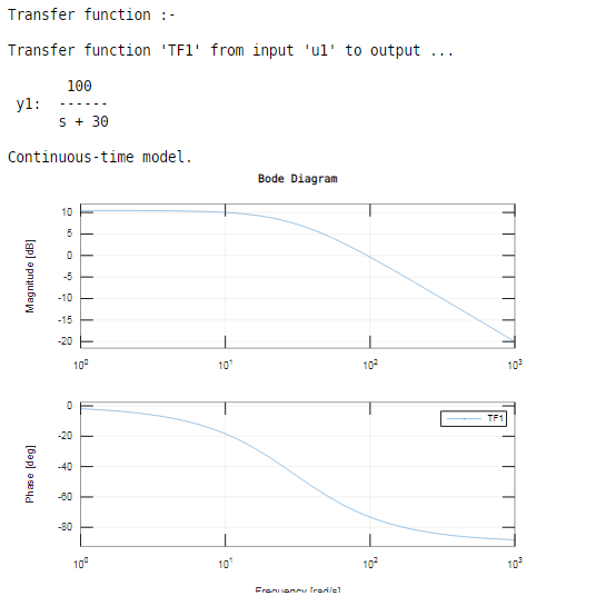
Web in this video, we will discuss how to draw the bode plot from a given transfer function. For the transfer function given, sketch the bode log magnitude diagram which shows how the log magnitude of the system is affected by changing input frequency. The slope of the first line is based on poles and zeros at the origin. Web generally, a transfer function may involve many poles and zeroes (and their dc counterparts). Examples (click on transfer function) 1. Web a bode plot shows the magnitude and phase of a transfer function in a pair of graphs. Refer to the following table. Several examples of the construction of bode plots are included here; Separate the transfer function into its constituent parts. You can convert between a bode plot and a transfer function with some simple arithmetic involving complex numbers.
Web magnitude and phase angle (shift). To find the magnitude, multiply h by its conjugate and then take the root. A bode plot consists of two separate plots, one for magnitude and one for phase angle. Here, we refer to the z variables as zeros and the p variables as poles, and a may be a function. Web generally, a transfer function may involve many poles and zeroes (and their dc counterparts). For example, an order of 2 means there is will be change in slope of. Rewrite the transfer function in proper form. Construct the bode plot for the given transfer function shown in factored form using matlab control toolbox functions. The numerator is an order 0 polynomial, the denominator is order 1. Frequency plot of a bode diagram, we superposition all the lines of the different terms on the same plot.

Bode Plot EXAMPLE YouTube
Web magnitude and phase angle (shift). Separate the transfer function into its constituent parts. Construct the bode plot for the given transfer function shown in factored form using matlab control toolbox functions. Also, remember that the bode function can output the results of its computations, and the bodeplot function allows you to tweak its behaviour. Your transfer function would use:

how to draw bode plot in MATLAB Bode plot using MATLAB MATLAB
You can convert between a bode plot and a transfer function with some simple arithmetic involving complex numbers. In order to make it easier to draw bode plots, your first step should be to factor the transfer function into the canonical form shown in equation 1. Web magnitude and phase angle (shift). This makes it easy to identify all of.
Bode Plot Matlab How to do Bode Plot Matlab with examples?
(real poles and zeros) 3. Construct the bode plot for the given transfer function shown in factored form using matlab control toolbox functions. Separate the transfer function into its constituent parts. A bode plot conversion applies to any transfer function, including network parameter matrices. Firstly, write the given transfer function in the time constant form.

Drawing Bode Plot From Transfer Function SecondOrder Double Zero
Web the steps to sketch the bode plot are as follows: Refer to the following table. Web • to complete the log magnitude vs. Several examples of the construction of bode plots are included here; Magnitude the first part of making a bode plot is finding the magnitude of the transfer function.

Deriving the Transfer Function from Bode Plot Example 1 YouTube
We seek simple intuitive understanding of a transfer function via bode plots vs f 2. This makes it easy to identify all of the poles and zeroes. How do you plot a bode plot for a given transfer function.if you want to see how to derive a transf. A bode plot consists of two separate plots, one for magnitude and.

ME 340 Example Drawing Bode Plot of a Transfer Function 2 YouTube
40 db/decade at the frequency of the zero or pole. Remember that the transfer function is the “black box” of your circuit which changes the voltage input into the. Frequency response basically means how our system will change with respect to a given input frequency. Draw the bode diagram for the transfer function: Web the steps to sketch the bode.
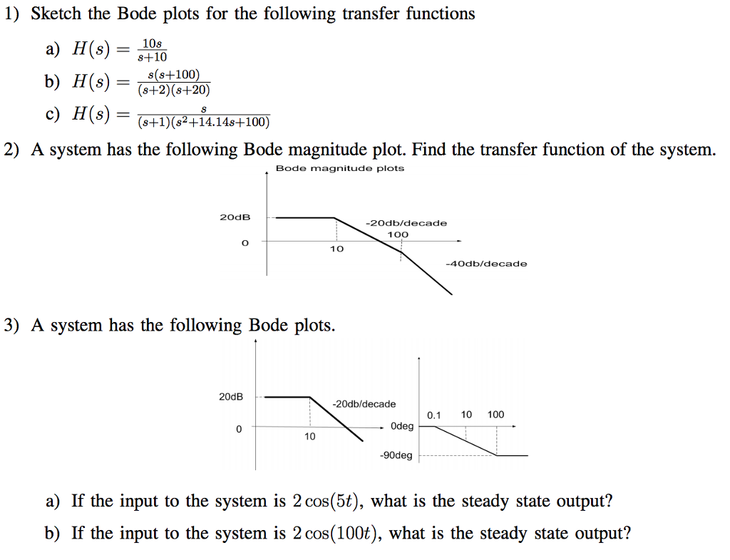
Solved Sketch The Bode Plots For The Following Transfer F...
Web generally, a transfer function may involve many poles and zeroes (and their dc counterparts). Examples (click on transfer function) 1. How do you plot a bode plot for a given transfer function.if you want to see how to derive a transf. Also, remember that the bode function can output the results of its computations, and the bodeplot function allows.

Bode Plot Example Bode Diagram Example MATLAB Electrical Academia
From the open loop response bode plots various design changes may be explored. Bode automatically determines frequencies to plot based on system dynamics. Examples (click on transfer function) 1. Draw the bode diagram for the transfer function: Therefore, the term “bode plot” usually refers to the magnitude plot.

Drawing Bode Plot From Transfer Function ThirdOrder System Real
Make both the lowest order term in the numerator and denominator unity. Frequency response basically means how our system will change with respect to a given input frequency. Web generally, a transfer function may involve many poles and zeroes (and their dc counterparts). Therefore, the term “bode plot” usually refers to the magnitude plot. How do you plot a bode.

Bode Plot Example Bode Diagram Example MATLAB Electrical Academia
From the open loop response bode plots various design changes may be explored. Magnitude the first part of making a bode plot is finding the magnitude of the transfer function. We seek simple intuitive understanding of a transfer function via bode plots vs f 2. Web magnitude and phase angle (shift). Therefore, the term “bode plot” usually refers to the.
Therefore, The Term “Bode Plot” Usually Refers To The Magnitude Plot.
Separate the transfer function into its constituent parts. Web a bode plot shows the magnitude and phase of a transfer function in a pair of graphs. Web a video that very clearly explains along with an example: Several examples of the construction of bode plots are included here;
Web The Transfer Function Is Complex Valued So, To Plot It, You Need Two Plots, Usually Magnitude And Phase.
This system could be any system (not just a circuit!) which experiences change in behavior due to a change in frequency (cycles/second). A bode plot consists of two separate plots, one for magnitude and one for phase angle. How do you plot a bode plot for a given transfer function.if you want to see how to derive a transf. Num = [1 0 p^2];
Your Transfer Function Would Use:
From the open loop response bode plots various design changes may be explored. So, you need to find the magnitude and then take the log before plotting the bode magnitude. To find the magnitude, multiply h by its conjugate and then take the root. Web the steps to sketch the bode plot are as follows:
40 Db/Decade At The Frequency Of The Zero Or Pole.
The order value of each zero and pole indicates the change in slope in multiples of. The slope is increased at zeros and reduced at poles. Draw the bode diagram for each part. Magnitude the first part of making a bode plot is finding the magnitude of the transfer function.