How To Draw Moment Diagrams
How To Draw Moment Diagrams - Web plots of v(x) and m(x) are known as shear and bending moment diagrams, and it is necessary to obtain them before the stresses can be determined. In general the process goes like this:1) calcul. To pave its way, this section will deal on how to draw moment diagram by parts and to calculate the moment of such diagrams about a specified axis. We will refer to them as we go through the following main steps in each example: If we know the state of longitudinal or normal stress due to bending at a given section in a structure we can work out the. Web reactions of support · shear force diagrams · bending moment diagrams · deflection and span ratios · cantilever & simply supported beam. Since beams primarily support vertical loads the axial. Web drawing on extensive previous studies of neural connections in worms by leifer’s team and fruit flies by murthy’s team, the two scientists and their teams will develop a system to create maps of functional connectivity that will shed light on how the brain controls activities such as decision making and movement. M = w2 ·a = moment load x g x a. Web this is an example problem that will show you how to graphically draw a shear and moment diagram for a beam.
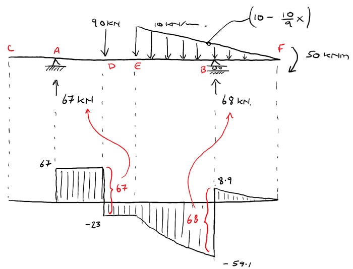
They allow us to see where the maximum loads occur so that we can optimize the design to prevent failures and reduce the overall weight and cost of the structure. We go through breaking a beam into segments, and then we learn about the relatio. 2) calculate the shear force and bending moment diagrams for frames as well. Web this video explains how to draw shear force diagram and bending moment diagram with easy steps for a simply supported beam loaded with a concentrated load. Three ways in which it could be improved: Just now you have calculated the bm values at different points of the beam, now plot the values and you will get the bending moment diagram like below: Since beams primarily support vertical loads the axial. The area for region 3 is 8.35 lb*ft and the shear is constant resulting in a linear moment. 1) allow a distributed load to be inputted as an equation i.e. Web in this video, we learn how to draw both the shear and bending moment diagram for a beam without using equations!
Web the ending point on the moment diagram for this section will be −50ftlb + 58.35ftlb = 8.35ft ∗ lb. From left to right, make “cuts” before and after each reaction/load. Web being able to draw shear force diagrams (sfd) and bending moment diagrams (bmd) is a critical skill for any student studying statics, mechanics of materials, or structural engineering. 2) calculate the shear force and bending moment diagrams for frames as well. The symbol ↕ used to draw the ray diagrams indicates. Web this website is great; There is a long way and a quick way to do them. Web drawing on extensive previous studies of neural connections in worms by leifer’s team and fruit flies by murthy’s team, the two scientists and their teams will develop a system to create maps of functional connectivity that will shed light on how the brain controls activities such as decision making and movement. In general the process goes like this:1) calcul. Web steps to construct shear force and bending moment diagrams.

Shear Force and Bending Moment Diagram Calculator
To pave its way, this section will deal on how to draw moment diagram by parts and to calculate the moment of such diagrams about a specified axis. Web shear and moment diagrams are graphs which show the internal shear and bending moment plotted along the length of the beam. In a simply supported beam, the only vertical force is.

Mechanics Map Shear and Moment Diagrams
There is a long way and a quick way to do them. Since beams primarily support vertical loads the axial. Web this website is great; Web everything you need to know about shear and bending moment diagrams for beams, including point loads, distributed loads (triangular too), and external couple. Web 𝐌𝐲 𝐄𝐧𝐠𝐢𝐧𝐞𝐞𝐫𝐢𝐧𝐠 𝐍𝐨𝐭𝐞𝐛𝐨𝐨𝐤 for notes!

Moment Diagrams Constructed by the Method of Superposition
Web 💡 the internal bending moment m m m, is the bending moment we represent in a bending moment diagram.the bending moment diagram shows how m m m (and therefore normal stress) varies across a structure. Put a dot at the end point ( 8.35 lbft) and draw a straight line to it ( this shear segment is also constant)..

Learn How To Draw Shear Force And Bending Moment Diagrams Engineering
An increase in magnetic flux through a coil of 100 turns in 0.1 s is 0.001 wb. They allow us to see where the maximum loads occur so that we can optimize the design to prevent failures and reduce the overall weight and cost of the structure. We will refer to them as we go through the following main steps.
The Ultimate Guide to Shear and Moment Diagrams
We go through breaking a beam into segments, and then we learn about the relatio. Record the values for each position of the load w and compute the shear force q and bending diagram m using: Utilize this on your exams in strengths of. Knowing forces effect on beams. To pave its way, this section will deal on how to.

Learn How To Draw Shear Force And Bending Moment Diagrams Engineering
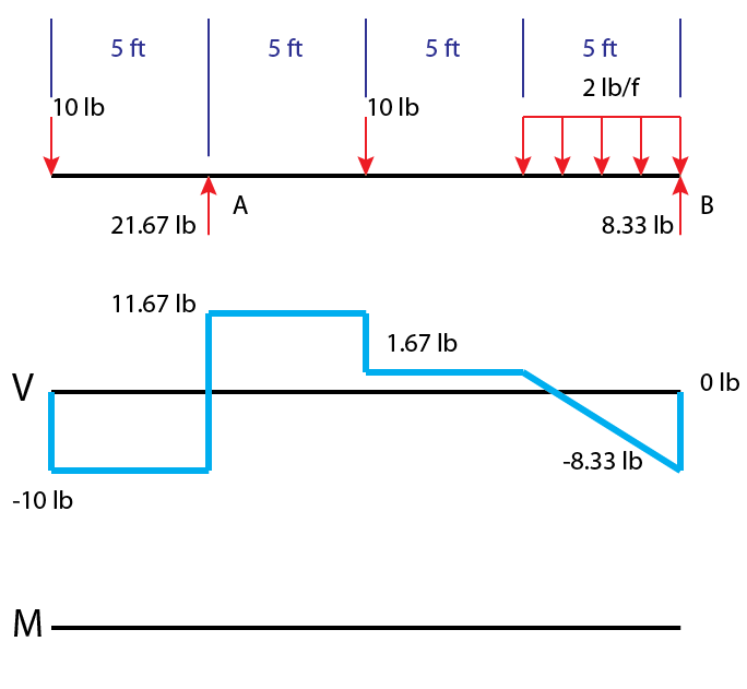
The moment at the end of this segment is. Web this website is great; In addition to the two principal values of bending moment at x = 0 m and at x = 5 m, the moments at other intermediate points should be determined to correctly draw the bending moment diagram. Web this is an example problem that will show.

Drawing Shear and Moment Diagrams for Beam YouTube
Three ways in which it could be improved: Web since the function for the bending moment is parabolic, the bending moment diagram is a curve. 2) calculate the shear force and bending moment diagrams for frames as well. Web everything you need to know about shear and bending moment diagrams for beams, including point loads, distributed loads (triangular too), and.
» How to Draw Moment Diagrams ReviewCivilPE
Draw a free body diagram of the beam with global coordinates (x); The moment at the end of this segment is. The maximum induced emf generated in the coil is. Has graph paper, study tips, and some sudoku puzzles or downtime between classes! Web the ending point on the moment diagram for this section will be −50ftlb + 58.35ftlb =.

Learn How To Draw Shear Force And Bending Moment Diagrams Engineering
Web once you have the reactions, draw your free body diagram and shear force diagram underneath the beam. Web everything you need to know about shear and bending moment diagrams for beams, including point loads, distributed loads (triangular too), and external couple. Web this is an example problem that will show you how to graphically draw a shear and moment.

How to draw shear and moment diagrams YouTube
Web shear and moment diagrams are graphs which show the internal shear and bending moment plotted along the length of the beam. To calculate the bending moment of a beam, we must work in the same way we did for the. All afds, sfds, and bmds follow these basic rules. Q = w1 = shear load x g bending moment:.
Web In This Video, We Learn How To Draw Both The Shear And Bending Moment Diagram For A Beam Without Using Equations!
Finally calculating the moments can be done in the following steps: Web there is zero bending moment at a hinge. The bending moment diagram of the beam is shown in. 2) calculate the shear force and bending moment diagrams for frames as well.
Put A Dot At The End Point ( 8.35 Lbft) And Draw A Straight Line To It ( This Shear Segment Is Also Constant).
The long way is more comprehensive, and generates expressions for internal shear and internal bending. Web this is an example problem that will show you how to graphically draw a shear and moment diagram for a beam. This example deals with a constant distributed force (shear is a linear function of x). Draw a free body diagram of the beam with global coordinates (x);
In Addition To The Two Principal Values Of Bending Moment At X = 0 M And At X = 5 M, The Moments At Other Intermediate Points Should Be Determined To Correctly Draw The Bending Moment Diagram.
The bending moment diagram of the. Knowing forces effect on beams. Web this website is great; Web once you have the reactions, draw your free body diagram and shear force diagram underneath the beam.
The Symbol ↕ Used To Draw The Ray Diagrams Indicates.
Web everything you need to know about shear and bending moment diagrams for beams, including point loads, distributed loads (triangular too), and external couple. In this example, the point moment causes no shear. Web step 1 | draw a free body diagram. Find the support reaction forces/moments.