How To Draw Phasor Diagram
How To Draw Phasor Diagram - July 09, 2023 by amna ahmad. Web for drawing the phasor diagram of series rlc circuit, follow these steps: All phasors are drawn referenced to the horizontal zero axis. The vectors are then drawn on a common reference axis according to their respective angles to depict their relative positions and relationships. Free technical supportgraphing for 30+ yearscross platform supportcelebrating 35 years The current phasors may be drawn with closed arrow heads while the voltage phasors with open arrow heads. To draw a phasor diagram, you represent each voltage or current phasor as a vector with its magnitude and phase angle. Web in order to distinguish between different alternating quantities like current, voltage or flux, different types of arrow heads may be used. 423k views 6 years ago. Web how to draw a phasor diagram?
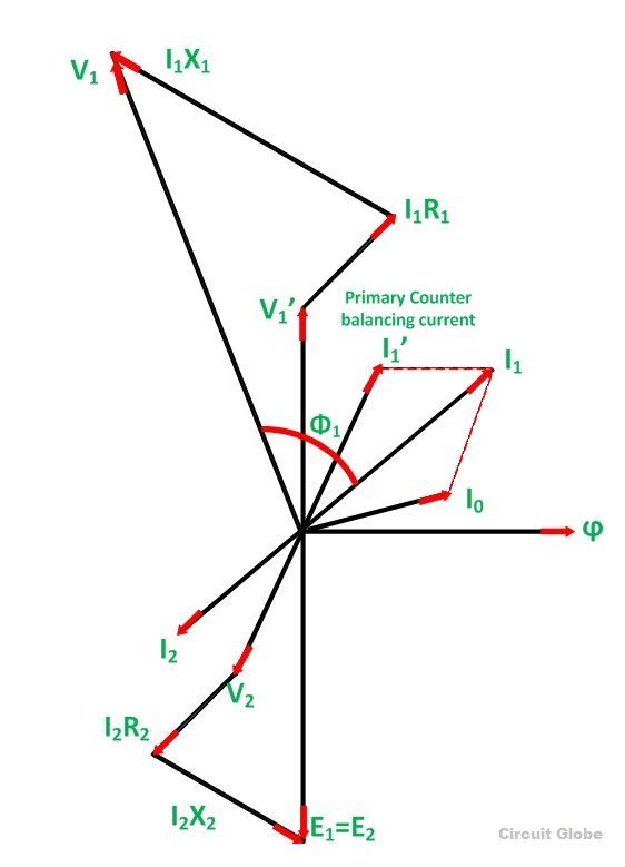
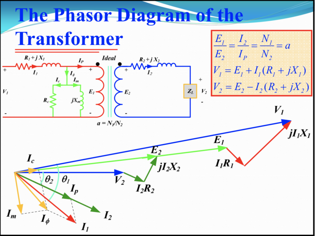
They are helpful in depicting the phase relationships between two or more oscillations. Phasors are rotating vectors having the length equal to the peak value of oscillations, and the angular speed equal to the angular frequency of. Web phasor diagrams can be used to represent two or more stationary sinusoidal quantities at any instant in time. In circuits which have l, c, r connected in series. Free technical supportgraphing for 30+ yearscross platform supportcelebrating 35 years So, the current flowing in all the elements are same i.e i r = i l = i c = i. Web step by step phasor diagram of transformer for no load, lagging load and leading load condition. What is phasor diagram 3. Web how do you draw a phasor diagram? These diagrams plot various ac quantities, like current and voltage, as vectors rotating in a circular path.
Generally the reference phasor is drawn along the horizontal axis and at that instant in time the other phasors are drawn. At that instant, draw the other phasors one after another from the origin point. Resistor, capacitor and inductor are connected in series; So, take current phasor as reference and draw it on horizontal axis as shown in diagram. Web in order to draw the phasor diagram one should know these two important points which are written below: While the general idea of the two waves adding is apparent in the graph, it takes a moment of inspection to determine the wave magnitudes and. The length of the phasor is directly proportional to the amplitude of the wave depicted. Web it’s essential to know what a phasor diagram represents before diving into the process of drawing one. The current phasors may be drawn with closed arrow heads while the voltage phasors with open arrow heads. Free technical supportgraphing for 30+ yearscross platform supportcelebrating 35 years
How To Draw A Phasor Diagram Free Wiring Diagram
They are helpful in depicting the phase relationships between two or more oscillations. Web how to draw a phasor diagram? Figure 1 shows a simple ac series circuit containing resistance and inductance. 33k views 3 years ago #techtalks #howtodrawphasordiagram. Web phasor diagrams can be used to represent two or more stationary sinusoidal quantities at any instant in time.

how to draw phasor diagram ? how to draw phasor diagram ? YouTube
Phasors are rotating vectors having the length equal to the peak value of oscillations, and the angular speed equal to the angular frequency of. Here, two sine waves (green and red) combine to create a third sine wave (blue). Web for drawing the phasor diagram of series rl circuit; Free technical supportgraphing for 30+ yearscross platform supportcelebrating 35 years So,.

How to draw phasor diagram from polar form phasors ? Electrical
There are five rules for drawing phasor diagrams. 423k views 6 years ago. The length of the phasor is directly proportional to the amplitude of the wave depicted. Web in order to distinguish between different alternating quantities like current, voltage or flux, different types of arrow heads may be used. The modulus of this vector is the amplitude of the.

How to draw a Phasor Diagram ? Step by Step Tech TALKS YouTube
Graph functions, plot points, visualize algebraic equations, add sliders, animate graphs, and more. The presentation file describes how to start drawing phasor diagram form scratch with basics. Drawing phasor diagrams and equivalent circuits. The modulus of this vector is the amplitude of the oscillations and the phase constant represents the angle that the complex vector forms. It is customary to.
How To Draw A Phasor Diagram Free Wiring Diagram
Web phasor diagrams can be used to represent two or more stationary sinusoidal quantities at any instant in time. They are helpful in depicting the phase relationships between two or more oscillations. While the general idea of the two waves adding is apparent in the graph, it takes a moment of inspection to determine the wave magnitudes and. In case.
38 how to draw phasor diagram Wiring Diagrams Manual
The modulus of this vector is the amplitude of the oscillations and the phase constant represents the angle that the complex vector forms. The current phasors may be drawn with closed arrow heads while the voltage phasors with open arrow heads. So, take current phasor as reference and draw it on horizontal axis as shown in diagram. What is phasor.

How To Work & Draw Phasor Diagram Of Transformer At No Load YouTube
Web how to draw a phasor diagram? The current phasors may be drawn with closed arrow heads while the voltage phasors with open arrow heads. Web phasors are rotating vectors having the length equal to the peak value of oscillations, and the angular speed equal to the angular frequency of the oscillations. 33k views 3 years ago #techtalks #howtodrawphasordiagram. Figure.

Phasor Diagram Of Capacitor
The modulus of this vector is the amplitude of the oscillations and the phase constant represents the angle that the complex vector forms. Why it is used 4. Importance of phasor diagram 2. Web for drawing the phasor diagram of series rlc circuit, follow these steps: They are helpful in depicting the phase relationships between two or more oscillations.
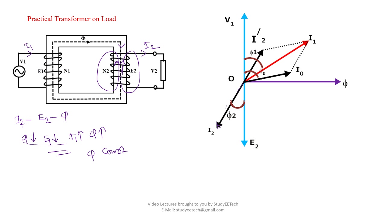
How to Draw Transformer Phasor Diagram YouTube
In case of series rlc circuit; There are five rules for drawing phasor diagrams. Web how to draw a phasor diagram? Importance of phasor diagram 2. Web for drawing the phasor diagram of series rl circuit;
How to draw phasor diagram
Web how to draw a phasor diagram? In this video, phasor, and phasor diagram for ac circuits have been explained. In case of series rl circuit, resistor and inductor are connected in series, so current flowing in both the elements are same i.e i r = i l = i. Figure 1 shows a simple ac series circuit containing resistance.
423K Views 6 Years Ago.
In case of series rlc circuit; Subscribe my new channel here. 33k views 3 years ago #techtalks #howtodrawphasordiagram. So, the current flowing in all the elements are same i.e i r = i l = i c = i.
And At The End, Voltage And Current Relationship Between The Basic Circuit.
A phasor can be seen as a rotating vector and the sine wave can be understood as the projection onto the real axis of a rotating vector on the complex plane. Web for drawing the phasor diagram of series rlc circuit, follow these steps: Web for drawing the phasor diagram of series rl circuit; Choose a phasor as a reference and draw it along the horizontal axis.
The Length Of The Phasor Is Directly Proportional To The Amplitude Of The Wave Depicted.
Web it’s essential to know what a phasor diagram represents before diving into the process of drawing one. Web in order to draw the phasor diagram one should know these two important points which are written below: Graph functions, plot points, visualize algebraic equations, add sliders, animate graphs, and more. They are helpful in depicting the phase relationships between two or more oscillations.
Free Technical Supportgraphing For 30+ Yearscross Platform Supportcelebrating 35 Years
Generally the reference phasor is drawn along the horizontal axis and at that instant in time the other phasors are drawn. (2) phasor excitation emf is always behind the phasor terminal voltage. Web explore math with our beautiful, free online graphing calculator. In case of series rl circuit, resistor and inductor are connected in series, so current flowing in both the elements are same i.e i r = i l = i.