Iso Drawings
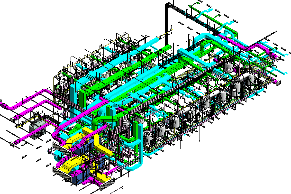
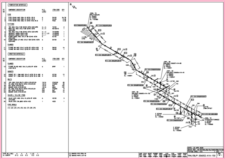
Iso Drawings - Web microfilming of technical drawings and other drawing office documents — part 6: Web representation and dimensioning of holes in the sections is preferred. Web a piping isometric drawing is a technical drawing that depicts a pipe spool or a complete pipeline using an isometric representation. Engineering drawings can be intimidating if you've never looked at one before, but in this article, we'll help you make sense of them. 1.2 differences between iso and us standards. Dessins techniques — principes généraux de représentation — partie 24: Web chapter 1 drawing notation and default tolerances. Web electrical and electronics engineering drawings including electrical tables, diagrams and charts 01.100.27 technical drawings for telecommunications and information technology fields These tools generate the 3d representation of the piping layout, including pipe dimensions, fittings,. Web graphical symbols for use on information technology and telecommunications technical drawings and in relevant technical product documentation 01.080.99 other graphical symbols
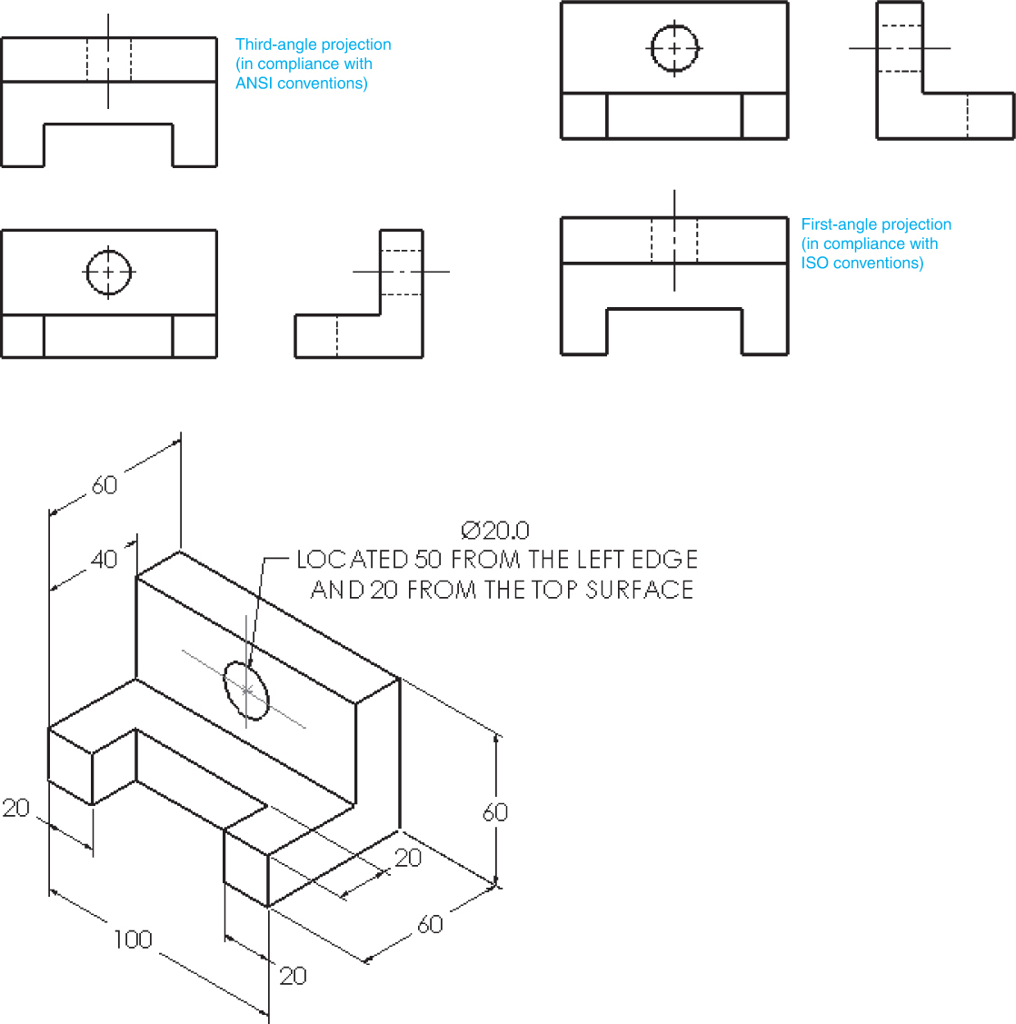
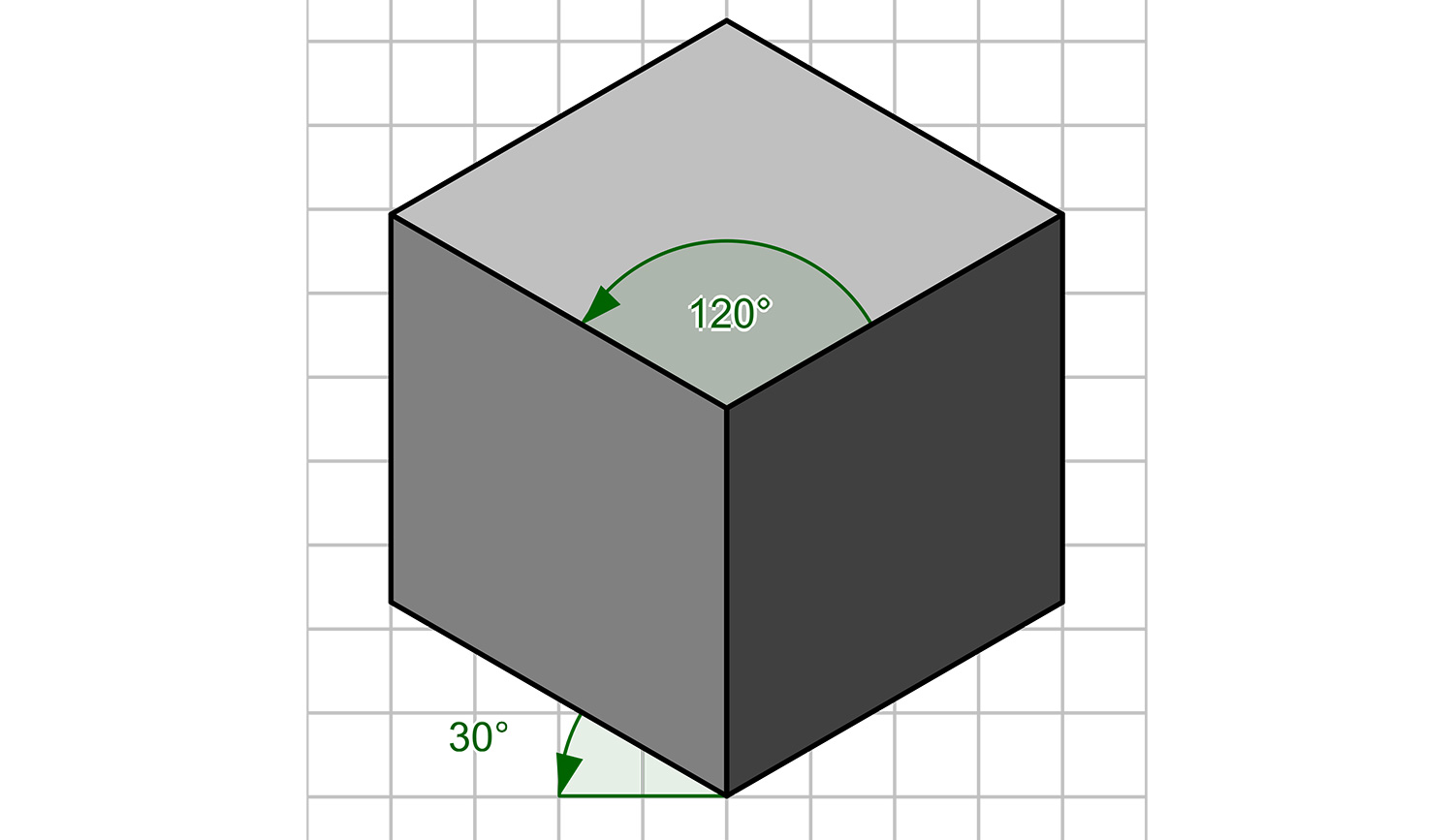
Web understanding the intricacies of pipeline isometric drawings, including iso standard isometric symbols, fittings, flanges, valves, and special components, is foundational for professionals in the field. Dessins techniques — principes généraux de représentation — partie 24: Web electrical and electronics engineering drawings including electrical tables, diagrams and charts 01.100.27 technical drawings for telecommunications and information technology fields For dimensioning in the sections, the leader line is directed towards the point of intersections of the visible edge of the part and the centre line of the hole, ending. It is an axonometric projection in which the three coordinate axes appear equally foreshortened and the angle between any two of them is 120 degrees. Web in other countries, drafting standards are controlled by the international standards organization (iso). Engineering drawings can be intimidating if you've never looked at one before, but in this article, we'll help you make sense of them. This part of iso 129 establishes the general principles of dimensioning applicable for all types of technical drawings. Traits utilisés pour les dessins industriels. Quality criteria and control of systems for enlargements from 35 mm microfilm
Web iso 129 consists of the following parts, under the general title technical drawings — indication of dimensions and tolerances: 1.5 table and drawing field. For dimensioning in the sections, the leader line is directed towards the point of intersections of the visible edge of the part and the centre line of the hole, ending. It is an axonometric projection in which the three coordinate axes appear equally foreshortened and the angle between any two of them is 120 degrees. It is the most important deliverable of any project where piping plays a vital role. This part of iso 129 establishes the general principles of dimensioning applicable for all types of technical drawings. These tools generate the 3d representation of the piping layout, including pipe dimensions, fittings,. Iso in eu and ansi in us. Web electrical and electronics engineering drawings including electrical tables, diagrams and charts 01.100.27 technical drawings for telecommunications and information technology fields Engineering drawings can be intimidating if you've never looked at one before, but in this article, we'll help you make sense of them.

How to read iso drawings plmci
It is the most important deliverable of any project where piping plays a vital role. 1.2 differences between iso and us standards. Web graphical symbols for use on information technology and telecommunications technical drawings and in relevant technical product documentation 01.080.99 other graphical symbols These tools generate the 3d representation of the piping layout, including pipe dimensions, fittings,. Isometric drawing.
Isometric view drawing example 1 (easy). Links to practice files in
Web piping isometric drawing software is an essential tool for piping engineers and designers to create detailed isometric drawings of piping systems. Engineering drawings can be intimidating if you've never looked at one before, but in this article, we'll help you make sense of them. The drawing axes of the isometrics intersect at an angle of 60°. Web iso 129.
3 Views Of Isometric Drawing at Explore collection
Web microfilming of technical drawings and other drawing office documents — part 6: These tools generate the 3d representation of the piping layout, including pipe dimensions, fittings,. Engineering drawings can be intimidating if you've never looked at one before, but in this article, we'll help you make sense of them. Web graphical symbols for use on information technology and telecommunications.

How to read iso drawings plmci
Engineering drawings can be intimidating if you've never looked at one before, but in this article, we'll help you make sense of them. The drawing axes of the isometrics intersect at an angle of 60°. Web piping isometric drawing software is an essential tool for piping engineers and designers to create detailed isometric drawings of piping systems. Web chapter 1.
Revit AddOns EzISO Piping Models to Isometric Drawings
Engineering drawings can be intimidating if you've never looked at one before, but in this article, we'll help you make sense of them. Web piping isometric drawing software is an essential tool for piping engineers and designers to create detailed isometric drawings of piping systems. Web a piping isometric drawing is a technical drawing that depicts a pipe spool or.
How to read iso pipe drawings talentbda
Web a piping isometric drawing is a technical drawing that depicts a pipe spool or a complete pipeline using an isometric representation. 1.5 table and drawing field. Web iso 129 consists of the following parts, under the general title technical drawings — indication of dimensions and tolerances: Web technical drawings — general principles of presentation — lines on mechanical engineering.
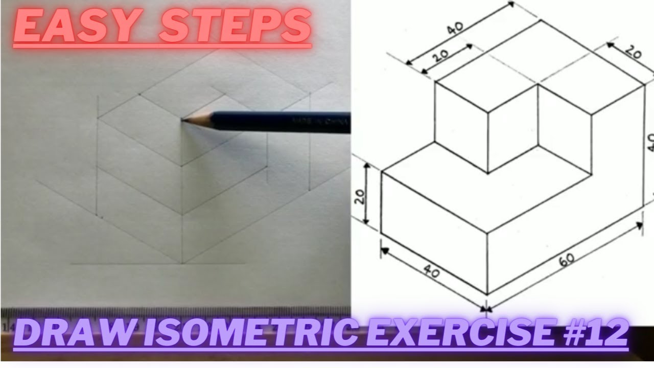
How to draw ISOMETRIC PROJECTIONS Technical Drawing Exercise 12
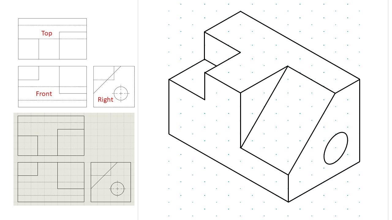
For dimensioning in the sections, the leader line is directed towards the point of intersections of the visible edge of the part and the centre line of the hole, ending. Web put information in your drawings and diagrams into perspective with an isometric drawing. The drawing shows three views of the image. Web understanding the intricacies of pipeline isometric drawings,.
What is an Isometric Drawing? Types And Step To Draw
Web the iso 10110 standard is an optical drawing standard used to explicitly describe an optical part based on the principle of geometric dimensioning and tolerancing (gd&t). These tools generate the 3d representation of the piping layout, including pipe dimensions, fittings,. Web piping isometric drawing software is an essential tool for piping engineers and designers to create detailed isometric drawings.
Isometric drawing a designer's guide Creative Bloq
How to read iso drawings. Web technical drawings — general principles of presentation — lines on mechanical engineering drawings. 1.3 overview of coded notation. Web microfilming of technical drawings and other drawing office documents — part 6: This part of iso 129 establishes the general principles of dimensioning applicable for all types of technical drawings.
Isometric Drawing at Explore collection of
Web chapter 1 drawing notation and default tolerances. Web in other countries, drafting standards are controlled by the international standards organization (iso). Engineering drawings can be intimidating if you've never looked at one before, but in this article, we'll help you make sense of them. It is the most important deliverable of any project where piping plays a vital role..
Web Iso 129 Consists Of The Following Parts, Under The General Title Technical Drawings — Indication Of Dimensions And Tolerances:
Web the iso 10110 standard is an optical drawing standard used to explicitly describe an optical part based on the principle of geometric dimensioning and tolerancing (gd&t). These tools generate the 3d representation of the piping layout, including pipe dimensions, fittings,. Web put information in your drawings and diagrams into perspective with an isometric drawing. It is an axonometric projection in which the three coordinate axes appear equally foreshortened and the angle between any two of them is 120 degrees.
Web Graphical Symbols For Use On Information Technology And Telecommunications Technical Drawings And In Relevant Technical Product Documentation 01.080.99 Other Graphical Symbols
Web understanding the intricacies of pipeline isometric drawings, including iso standard isometric symbols, fittings, flanges, valves, and special components, is foundational for professionals in the field. The drawing axes of the isometrics intersect at an angle of 60°. How to read iso drawings. 1.2 differences between iso and us standards.
Traits Utilisés Pour Les Dessins Industriels.
The drawing shows three views of the image. Web representation and dimensioning of holes in the sections is preferred. 1.3 overview of coded notation. It is the most important deliverable of any project where piping plays a vital role.
Quality Criteria And Control Of Systems For Enlargements From 35 Mm Microfilm
We are concluding our first pipefitter series run with a video on how to draw isometric drawings. Web technical drawings standards are radically different: Since 2003 the iso 128 standard contains fifteen parts, which were initiated between 1996 and 2003. Iso in eu and ansi in us.