Isometric Drawing Angle
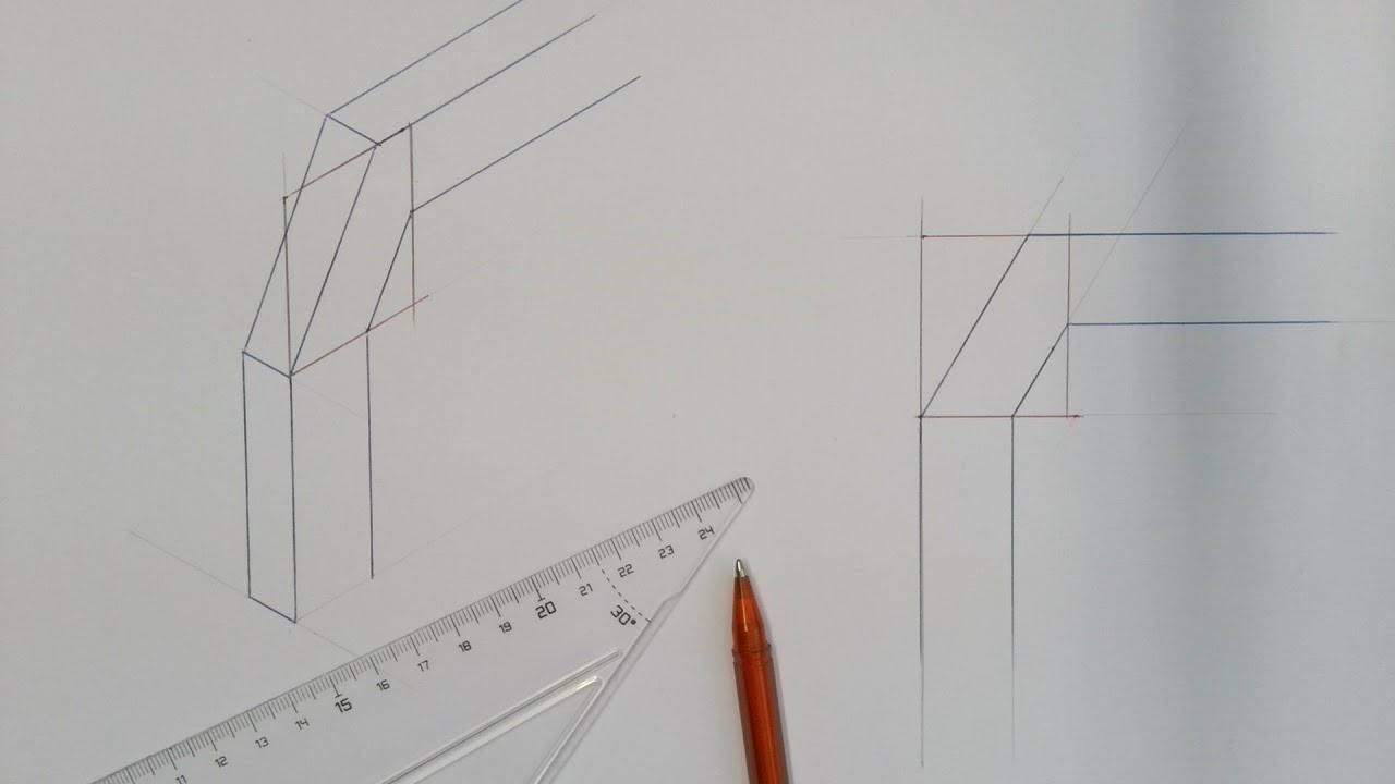
Isometric Drawing Angle - To begin drawing a parallel projection, draw a vertical line for the “z” axis. Parallel lines remain parallel and do not. None of the three angles will be 60° in the isometric drawing. Web the diagram on the right shows a set of three coordinate axes on an isometric drawing. This chapter will explain isometric basics including how regular, angular, and circular objects are drawn in isometric. You can shift, rotate, color, decompose, and view in 2‑d or 3‑d. Numerous isometric aids such as snap and isometric axes will be explained to assist in the construction of isometric drawings. Isometric drawings uses the same tools for creating, modifying and changing attributes as an orthogonal drawings, but on a grid configuration specific for an isometric perspective. To find dimension x, draw triangle bda from the top view full size, as shown. These drawings are impelled to supply a more detailed and authentic representation, emphasising the pipes, valves and other components’ shape, size and.
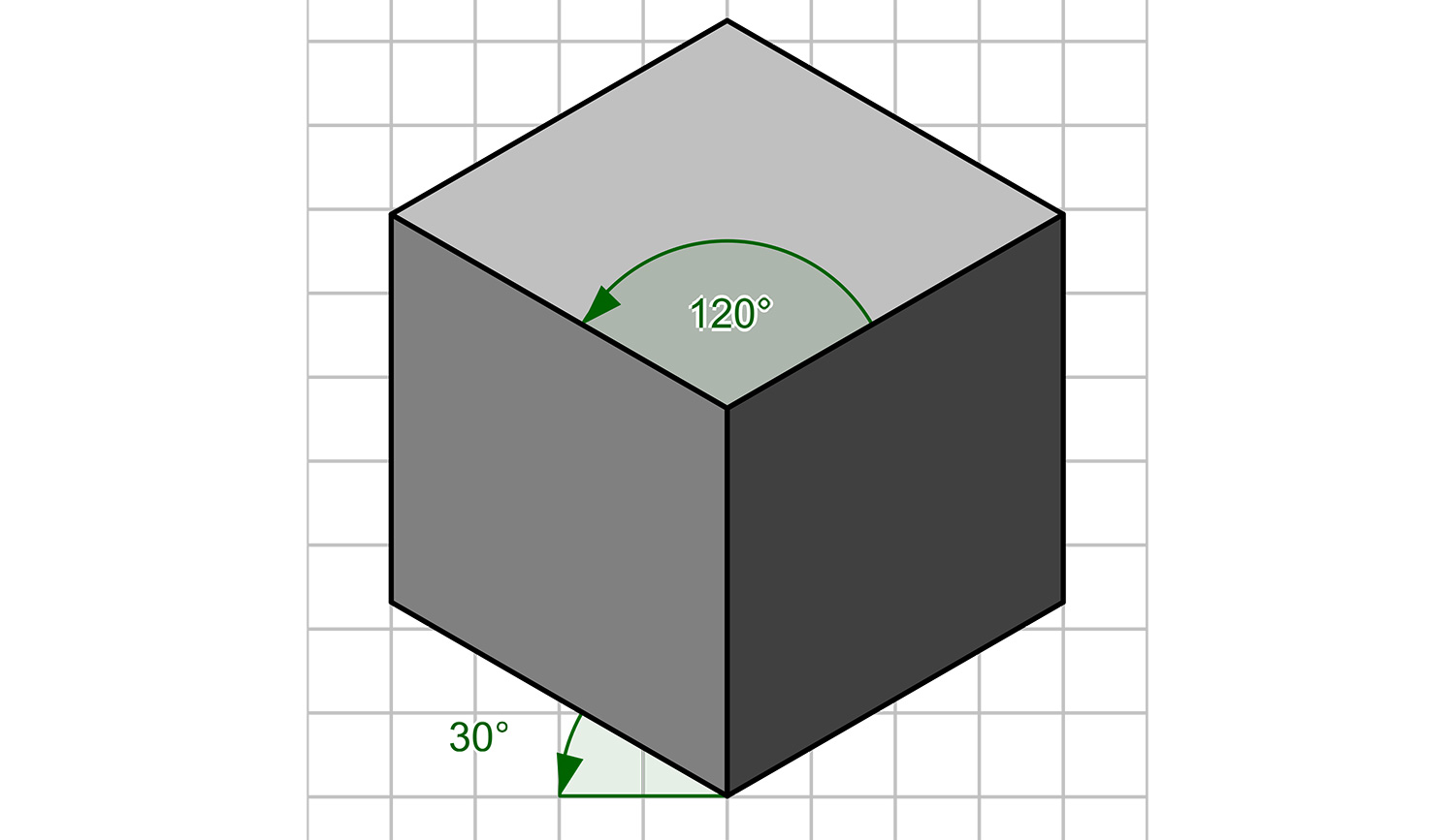
30/120/30 is also referred ti as true isometric grid. Isometric illustrations are very effective in data visualizations, instructions, infographics tutorials, and spot iconography. Isometric drawings uses the same tools for creating, modifying and changing attributes as an orthogonal drawings, but on a grid configuration specific for an isometric perspective. Then, draw a line connecting to the base for the “x” axis and another for the “y” axis. What is the angle between each pair of axes? Web on the “tool options” tool bar specify an angle of “135”, a length of “80” units and the snap point at the “start”. Lines parallel to these axes are drawn at equal angles (typically 30 degrees). Learn how to create stunning isometric views of objects using orthographic projections with this. Slide the 30 angle along the straight edge to make the part lines and construction lines at 30, 90, and 150. It is an axonometric projection in which the three coordinate axes appear equally foreshortened and the angle between any two of them is 120 degrees.
3.4k views 2 years ago technical & engineering drawing. How to draw angles in isometric. Numerous isometric aids such as snap and isometric axes will be explained to assist in the construction of isometric drawings. Use isometric grid paper (30, 90, 150 lines) or underlay paper to provide the axes and sketch the object. All three axes (length, width, and height) are equally foreshortened. Web as seen in the image of the cube, the result is that the axes intersect at 120 degree angles. Web as seen in the left view, the solid diagonal a “c1” is perpendicular to the plane of projection. In this video, i teach you all you need to know about isometric projection. Web the angle between all the three axes of the coordinate plane must be equal to 120 degrees. This chapter will explain isometric basics including how regular, angular, and circular objects are drawn in isometric.
Isometric drawing a designer's guide Creative Bloq
Isometric drawings uses the same tools for creating, modifying and changing attributes as an orthogonal drawings, but on a grid configuration specific for an isometric perspective. Isometric drawings lack the depth and vanishing points associated with perspective drawings. Slide the 30 angle along the straight edge to make the part lines and construction lines at 30, 90, and 150. 54k.
Isometric Drawing Guide
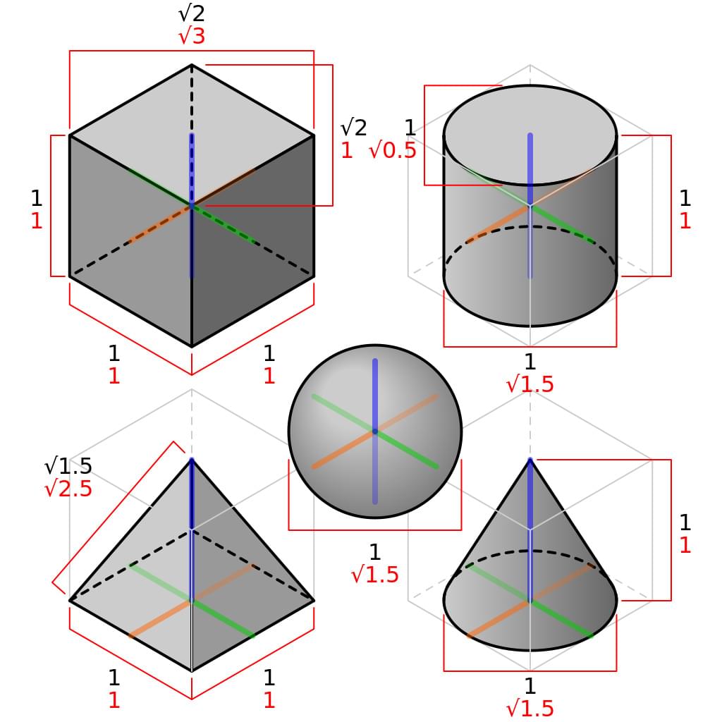
Web in an isometric drawing, there is a specific set of angles between each axis. Web line and copy are used for producing isometric drawings. 3rd to 5th, 6th to 8th, high school. 230k views 11 months ago isometric view in engineering drawing. Web thus, in an isometric drawing of a cube, the three visible faces appear as equilateral parallelograms;

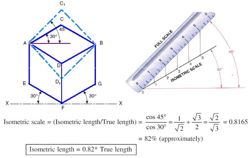
HOW TO DRAW THE ISOMETRIC SCALE YouTube
The three perpendicular edges ab, ad & aa1 will be equally inclined at an angle of 35° 16′ to the plane of projection. Web the diagram on the right shows a set of three coordinate axes on an isometric drawing. What is meant by isometric drawing? Because the angles between the three axes are all the same, each one must.

Designer’s Guide to isometric Projection by Alexander Gravit
What is the angle between each pair of axes? Web the angle between axonometric axes equals 120⁰. Isometric drawings are commonly used in technical drawing to show an item. Use a straight edge and a 30/60/90 triangle (see diagram.) a. 54k views 9 months ago isometric view in engineering drawing.
Isometric Drawing, Projection Its Types, Methods.
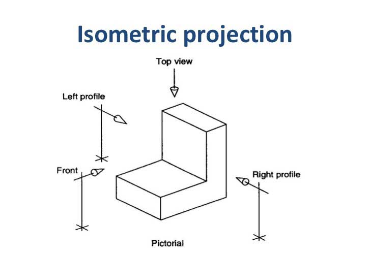
In this video, i teach you all you need to know about isometric projection. Web the angle between all the three axes of the coordinate plane must be equal to 120 degrees. In this comprehensive tutorial, we delve into the art of creating. Draw figures using edges, faces, or cubes. In this position, the front and top views are projected.

Making Isometric Drawings Using AutoLISP Part 5 Isometric drawing
These drawings are impelled to supply a more detailed and authentic representation, emphasising the pipes, valves and other components’ shape, size and. In this position, the front and top views are projected. The three perpendicular edges ab, ad & aa1 will be equally inclined at an angle of 35° 16′ to the plane of projection. Use isometric grid paper (30,.

isometric projection/axonometric projection Isometric Drawing, Arts And
To find dimension x, draw triangle bda from the top view full size, as shown. In this comprehensive tutorial, we delve into the art of creating. You can shift, rotate, color, decompose, and view in 2‑d or 3‑d. All three axes (length, width, and height) are equally foreshortened. Then, place cubes on the grid where.
LibreCAD Isometric Projection Drawing GeekThis
A perfect cube in an isometric projection would look like a perfect hexagon. Numerous isometric aids such as snap and isometric axes will be explained to assist in the construction of isometric drawings. Isometric drawings uses the same tools for creating, modifying and changing attributes as an orthogonal drawings, but on a grid configuration specific for an isometric perspective. In.
How to draw angles in an isometric YouTube
This article explains all you need to know about isometric illustrations. Lines parallel to these axes are drawn at equal angles (typically 30 degrees). What is meant by isometric drawing? That is, while all of the parallel edges of the cube are projected as parallel lines, the horizontal edges are drawn at an angle (usually 30°) from the normal horizontal.
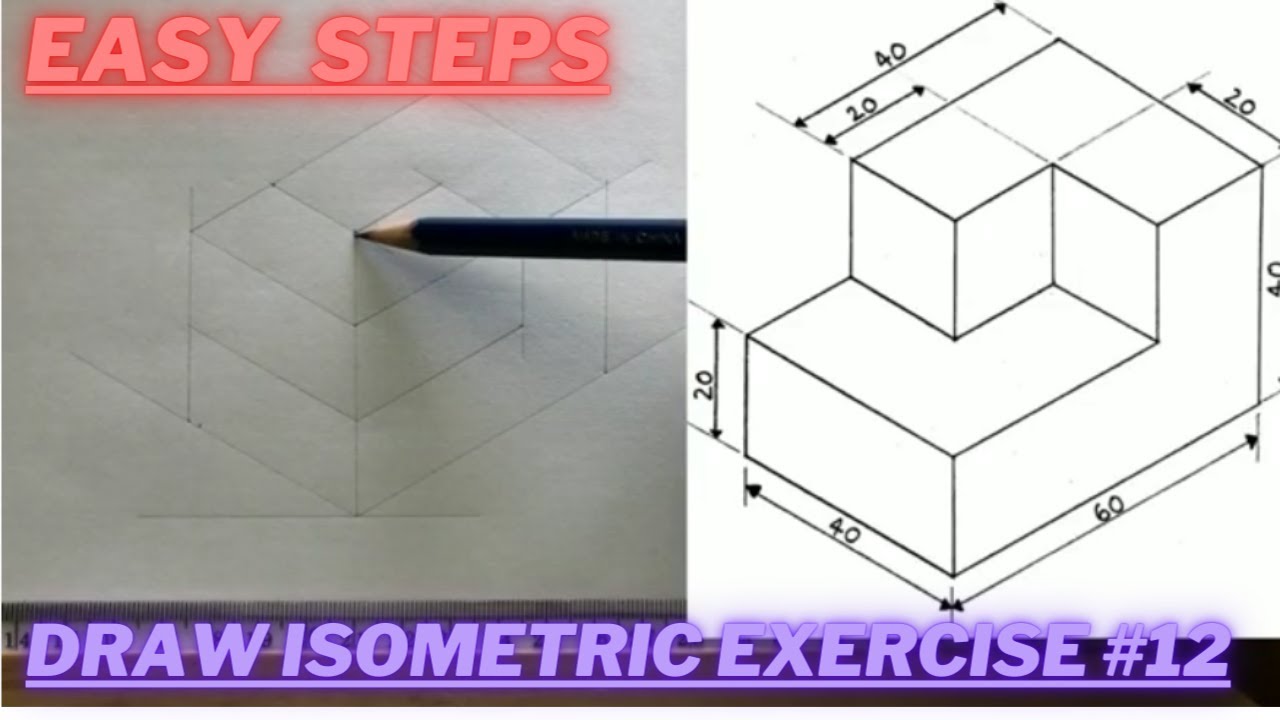
How to draw ISOMETRIC PROJECTIONS Technical Drawing Exercise 12
Web the diagram on the right shows a set of three coordinate axes on an isometric drawing. To find dimension x, draw triangle bda from the top view full size, as shown. In this comprehensive tutorial, we delve into the art of creating. Parallel lines remain parallel and do not. Web the angle between all the three axes of the.
Web Line And Copy Are Used For Producing Isometric Drawings.
30/120/30 is also referred ti as true isometric grid. Then, place cubes on the grid where. To find dimension x, draw triangle bda from the top view full size, as shown. Web the diagram on the right shows a set of three coordinate axes on an isometric drawing.
Web In Isometric Projection, The Most Commonly Used Form Of Axonometric Projection In Engineering Drawing, [4] The Direction Of Viewing Is Such That The Three Axes Of Space Appear Equally Foreshortened, And There Is A Common Angle Of 120° Between Them.
In this video, i teach you all you need to know about isometric projection. A perfect cube in an isometric projection would look like a perfect hexagon. It is an axonometric projection in which the three coordinate axes appear equally foreshortened and the angle between any two of them is 120 degrees. Lightly draw an enclosing box using the given dimensions, except for dimension x, which is not given.
Web As Seen In The Left View, The Solid Diagonal A “C1” Is Perpendicular To The Plane Of Projection.
Web on the “tool options” tool bar specify an angle of “135”, a length of “80” units and the snap point at the “start”. To begin drawing a parallel projection, draw a vertical line for the “z” axis. Isometric illustrations are very effective in data visualizations, instructions, infographics tutorials, and spot iconography. Web how to draw angles in an isometric
How To Draw Angles In Isometric.
54k views 9 months ago isometric view in engineering drawing. The isometric projection displays the three faces of an object, and they all are uniformly foreshortened. Because the angles between the three axes are all the same, each one must be 120 degrees. That is, while all of the parallel edges of the cube are projected as parallel lines, the horizontal edges are drawn at an angle (usually 30°) from the normal horizontal axes, and the vertical edges, which are parallel to the principal axes.