Isometric Drawing Pipeline
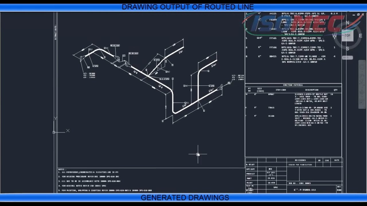
Isometric Drawing Pipeline - Piping isometric drawing consists of three sections. These highly structured drawings provide a comprehensive 3d representation of the arrangement, dimensions, and connections of pipes within a system. Isometric drawings are commonly used in industries such as the oil and gas industry, petrochemical industry, and plumbing for planning, design, construction, and pipeline maintenance. Web piping isometric drawing software is an essential tool for piping engineers and designers to create detailed isometric drawings of piping systems. Pipeline —generates a pipeline isometric for each selected pipeline. The minimum inputs for isometric sketching are: Piping, pressure vessels, storage tanks, structural fabrication and erection tutorialspiping isometric study. Web easy isometric is the first pipe isometric drawing app that helps users make detailed isometric drawings in the field and without the need for tedious reference materials. Piping isometric drawing dimensions are always from center to center of pipe. These drawings are impelled to supply a more detailed and authentic representation, emphasising the pipes, valves and other components’ shape, size and.
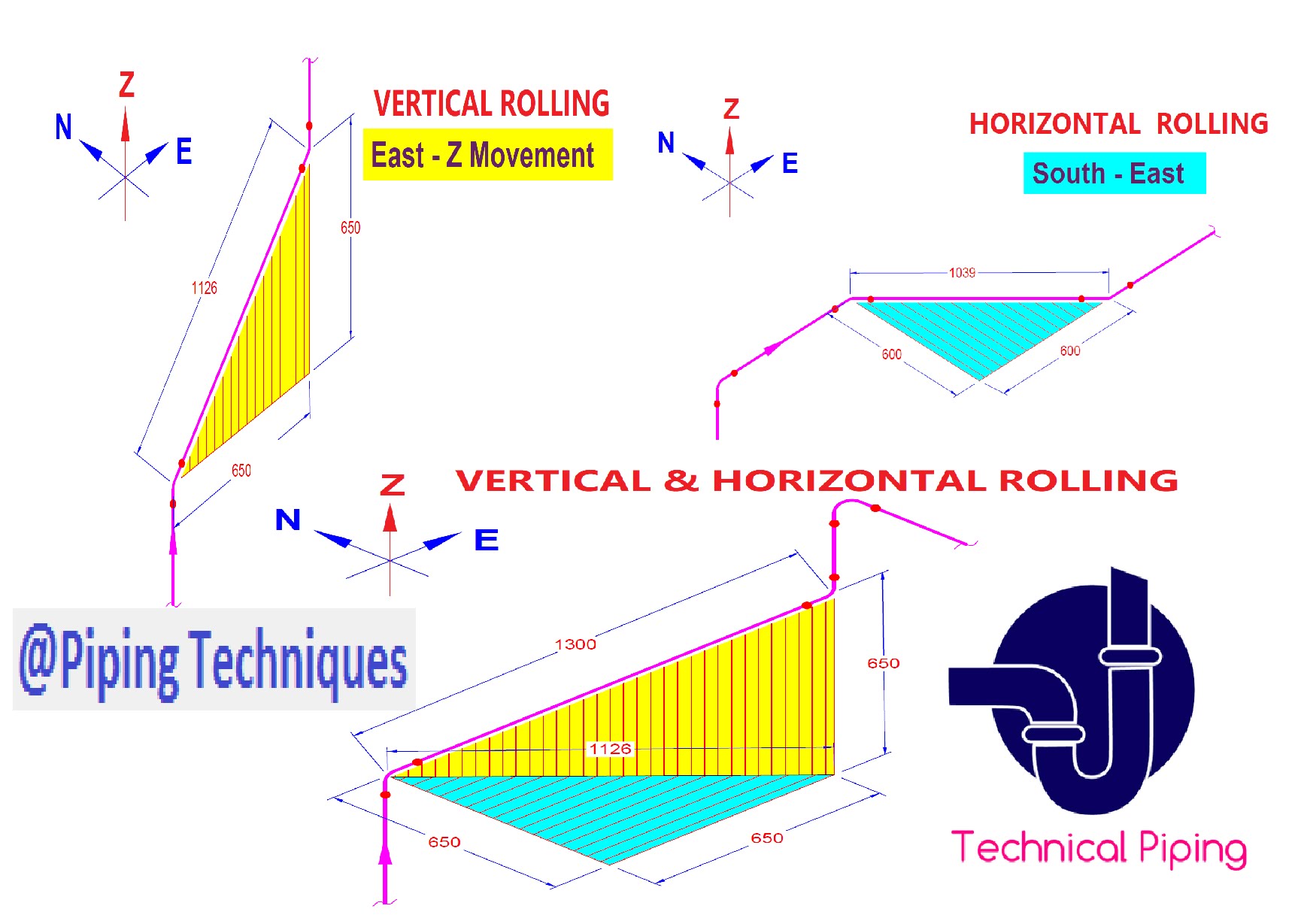
Web isometric, plan, and elevation presentations are three distinct types of drawings used to depict piping systems in engineering and construction. Pipe size is always written at any connecting point of isometric. Web how to read piping isometric drawing symbols. Piping fabrication work is based on isometric drawings. Piping plan drawings/general arrangement drawings (gad) the piping plan or general arrangement drawings (fig. These drawings are particularly useful for understanding how the pipeline moves through space, which helps in planning inspections in complex or tight areas. Isometric drawings are commonly used in industries such as the oil and gas industry, petrochemical industry, and plumbing for planning, design, construction, and pipeline maintenance. Piping, pressure vessels, storage tanks, structural fabrication and erection tutorialspiping isometric study. Pipeline —generates a pipeline isometric for each selected pipeline. Web drawing piping isometrics :
These drawings are particularly useful for understanding how the pipeline moves through space, which helps in planning inspections in complex or tight areas. The selection tab is selected by default. Importance of piping isometrics to the construction, commissioning, safe operation and maintenance of a process plant. Web to read piping isometric drawing you must know the following things: Isometric drawings are commonly used in industries such as the oil and gas industry, petrochemical industry, and plumbing for planning, design, construction, and pipeline maintenance. Web a piping isometric drawing is a simple representation of the pipeline, which nevertheless contains all relevant information and dimensions. These drawings provide a detailed 3d illustration of a piping system, offering a comprehensive view of. Piping plan drawings/general arrangement drawings (gad) the piping plan or general arrangement drawings (fig. The minimum inputs for isometric sketching are: This is because it enables a pipe work manufacturer to determine exactly how the pipeline will.
Piping Isometric Drawing at Explore collection of
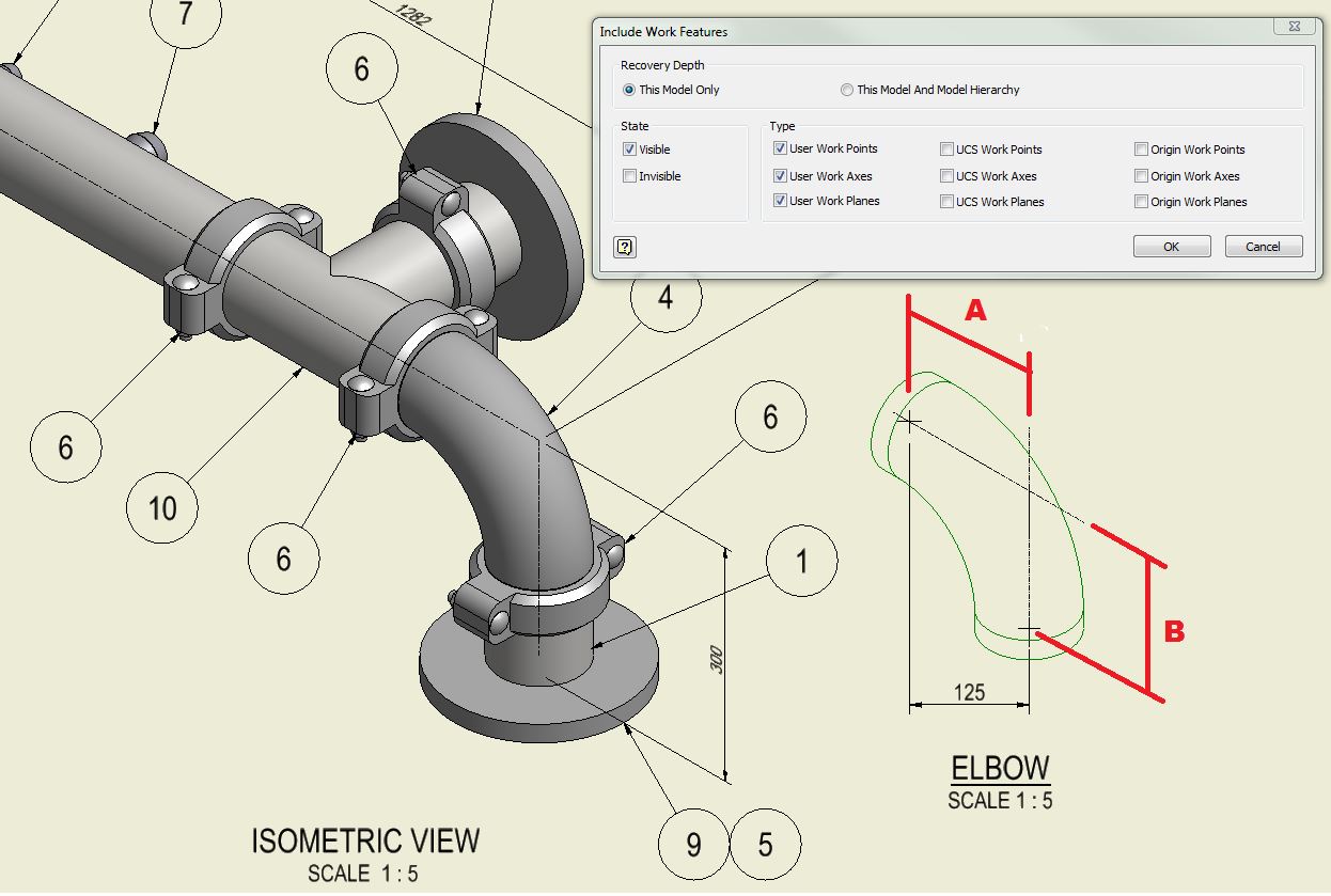
We are concluding our first pipefitter series run with a video on how to draw isometric drawings. The image below shows a orthographic view of a butt welded pipe with three sizes (a, b, c). The minimum inputs for isometric sketching are: The generate isometric dialog box opens and prompts you to select a pipeline. So, not from the outside.

How to read isometric drawing piping dadver
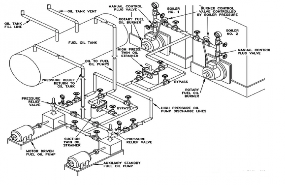
It shows all information necessary for fabrication and erection. Web a piping isometric drawing is a simple representation of the pipeline, which nevertheless contains all relevant information and dimensions. As you draw, the bom generates and updates itself automatically. 1) show all major equipment, its north/south and east/west orientation, and all piping leading to and from equipment are developed by.

Isometric Piping Drawings Advenser
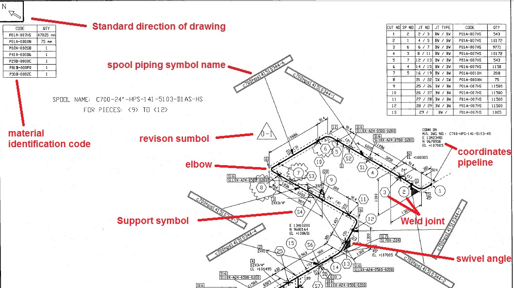
Web pipeline isometrics are detailed drawings used in engineering and design to represent the 3d layout of a pipeline system on a 2d surface. Web how to read piping isometric drawing symbols. This single line is the centerline of the pipe, and from that line, the dimensions measured. Piping isometric drawing consists of three sections. Web a pipe into a.
Isometric Pipe Drawing at GetDrawings Free download
Piping iso symbols and meaning. The generate isometric dialog box opens and prompts you to select a pipeline. These tools generate the 3d representation of the piping layout, including pipe dimensions, fittings,. The minimum inputs for isometric sketching are: Piping, pressure vessels, storage tanks, structural fabrication and erection tutorialspiping isometric study.
Pipeline Isometric Drawings Explained NDT Techniques & Interpretation
Web a piping isometric drawing is a technical illustration that presents a 3d representation of a piping system. Process & instrumentation diagram (p & id) 3. Web a pipe into a isometric view, is always drawn by a single line. Web isometric, plan, and elevation presentations are three distinct types of drawings used to depict piping systems in engineering and.

How to Draw Isometric Pipe Drawings in Autocad Gautier Camonect
These tools generate the 3d representation of the piping layout, including pipe dimensions, fittings,. Web an isometric drawing covers a complete line as per the line list and p&id. Each serves a unique purpose and offers different perspectives to engineers, designers, and builders, ensuring a comprehensive understanding of the piping system’s layout, design, and functionality. These drawings are particularly useful.
Piping Isometric Drawings Autodesk Community
Web an isometric drawing covers a complete line as per the line list and p&id. It is an axonometric projection in which the three coordinate axes appear equally foreshortened and the angle between any two of them is 120 degrees. The image below shows a orthographic view of a butt welded pipe with three sizes (a, b, c). Piping, pressure.

How to read piping Isometric drawing YouTube
These drawings are impelled to supply a more detailed and authentic representation, emphasising the pipes, valves and other components’ shape, size and. Subscribe to autodesk virtual academy. The selection tab is selected by default. Piping plan drawings/general arrangement drawings (gad) the piping plan or general arrangement drawings (fig. Piping isometric drawings are detailed technical illustrations that show a 3d view.

How to read isometric drawing piping dadver
As you draw, the bom generates and updates itself automatically. These drawings are particularly useful for understanding how the pipeline moves through space, which helps in planning inspections in complex or tight areas. Each serves a unique purpose and offers different perspectives to engineers, designers, and builders, ensuring a comprehensive understanding of the piping system’s layout, design, and functionality. Isometric.
Learn isometric drawings (piping isometric)
These highly structured drawings provide a comprehensive 3d representation of the arrangement, dimensions, and connections of pipes within a system. It is the most important deliverable of piping engineering department. Web drawing piping isometrics : How to read piping isometrics using real plant drawings. Web pipeline isometric drawings are crucial visual representations in the fields of engineering and construction.
Mechanical Data Sheets (Mds) In Some Of The Cases, More Detailed Piping Layout Will Be Available.
It is an axonometric projection in which the three coordinate axes appear equally foreshortened and the angle between any two of them is 120 degrees. Unlike orthographic drawings that show different views (front, side, and top) separately, isometric drawings combine these views into a. No more tedious material tracking when creating a pipe isometric drawing. The piping isometric drawing is used both for documentation and for the production of the pipelines.
The Minimum Inputs For Isometric Sketching Are:
Piping isometric drawing dimensions are always from center to center of pipe. Pipeline —generates a pipeline isometric for each selected pipeline. Web drawing piping isometrics : These tools generate the 3d representation of the piping layout, including pipe dimensions, fittings,.
Web Easy Isometric Is The First Pipe Isometric Drawing App That Helps Users Make Detailed Isometric Drawings In The Field And Without The Need For Tedious Reference Materials.
Piping isometric drawing is a representation of 3d view of piping layout of the plant. Quickly produce installation isometrics and fabrication spool drawings. Piping isometric drawings are detailed technical illustrations that show a 3d view of piping systems. Isometric drawings are commonly used in industries such as the oil and gas industry, petrochemical industry, and plumbing for planning, design, construction, and pipeline maintenance.
Understand The Content And Importance Of Piping Isometrics.
Web a pipe into a isometric view, is always drawn by a single line. These drawings are particularly useful for understanding how the pipeline moves through space, which helps in planning inspections in complex or tight areas. How to read iso drawings. The image below shows a orthographic view of a butt welded pipe with three sizes (a, b, c).