Isometric Engineering Drawing
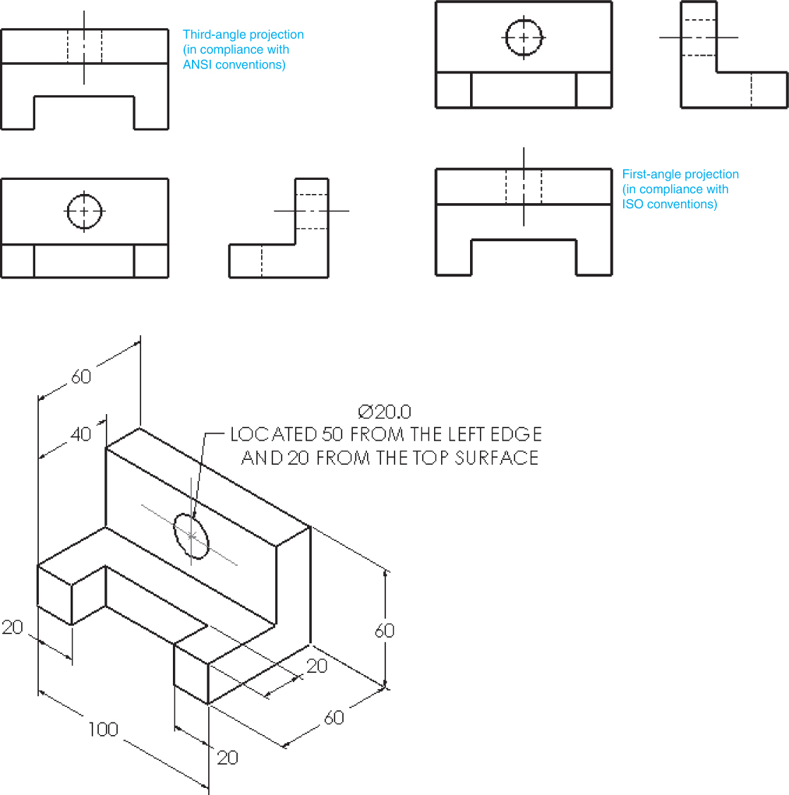
Isometric Engineering Drawing - To find the extent to which the lengths of the edges are foreshortened. When looking at an isometric drawing, three views are evident. Start by clicking on the cube along the left side; This is due to the fact that the foreshortening of the axes is equal. Web isometric drawings are used within the design of equipment, machinery, and processes for manufacturing in mechanical and industrial engineering. However, if the object in figure 2 had a hole on the back. One can pack a great deal of information into an isometric drawing. It is an axonometric projection in which the three coordinate axes appear equally foreshortened and the angle between any two of them is 120 degrees. A dimension listed on an engineering drawing is known as the _______ _______. Here is an example of an engineering drawing (an isometric view of the same object is shown above).
Draw figures using edges, faces, or cubes. Web discover how to draw amazing isometric views of objects with this tutorial. Isometric drawings are easy once you learn the basic techniques. (in making an orthographic projection, any point in the object is mapped onto the drawing by dropping a perpendicular from that point to the plane of the drawing.) an isometric projection results if the plane is oriented so that it makes equal angles (hence “isometric,” or “equal. However, if the object in figure 2 had a hole on the back. It is an axonometric projection in which the three coordinate axes appear equally foreshortened and the angle between any two of them is 120 degrees. In this comprehensive tutorial, we delve into the art of creating flawless isometric views using orthographic projecti. Web isometric drawings are used within the design of equipment, machinery, and processes for manufacturing in mechanical and industrial engineering. To find the extent to which the lengths of the edges are foreshortened. A dimension listed on an engineering drawing is known as the _______ _______.
Web learn to draw isometric projections using these simple steps provided. Web any engineering drawing should show everything: The 3 axes that meet. However, if the object in figure 2 had a hole on the back. Make a the lowest point of the drawing. Isometric drawings are easy once you learn the basic techniques. Web the isometric is one class of orthographic projections. Start by clicking on the cube along the left side; Web task 5.6 convert the orthographic drawing shown below into an isometric drawings. Draw figures using edges, faces, or cubes.
Engineering Educational Info Isometric to Orthographic views
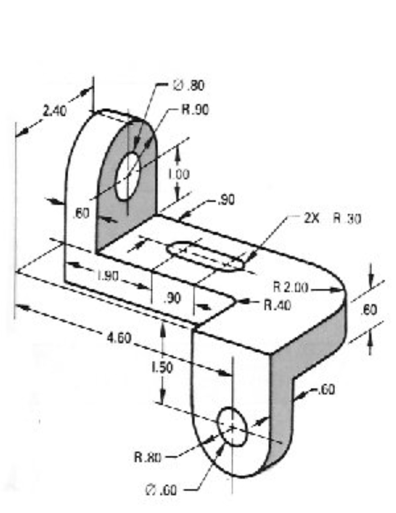
One can pack a great deal of information into an isometric drawing. However, if the drawing is produced using full scale, it is called an. A dimension listed on an engineering drawing is known as the _______ _______. Engineers may identify probable design defects, examine spatial linkages, and improve the overall aesthetic and performance of mechanical systems by visualizing complicated.
Isometric Drawing at Explore collection of
Web any engineering drawing should show everything: Web the word “isometric” is from the greek, meaning “equal measure.” depth is shown by slanting the edges up at 30° angle from the horizontal. One of the defining characteristics of an isometric drawing, compared to other types of 3d representation, is that the final image is not distorted and is always to.
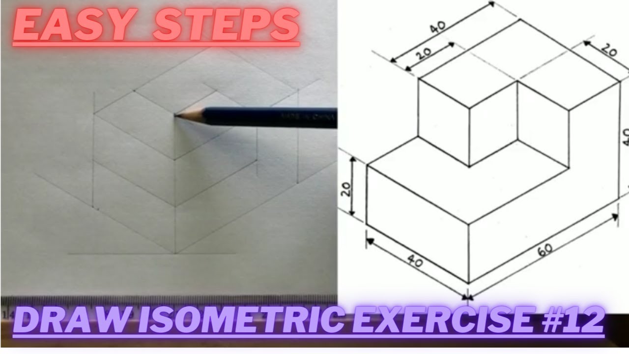
How to draw ISOMETRIC PROJECTIONS Technical Drawing Exercise 12
3rd to 5th, 6th to 8th, high school. Engineers may identify probable design defects, examine spatial linkages, and improve the overall aesthetic and performance of mechanical systems by visualizing complicated assemblies. To find the extent to which the lengths of the edges are foreshortened. Web learn to draw isometric projections using these simple steps provided. Draw figures using edges, faces,.
Isometric Drawing For Beginners Pdf bmpi
Isometric drawing, which is the same proportion as an isometric projection, but is larger by a. Draw figures using edges, faces, or cubes. One can pack a great deal of information into an isometric drawing. They are used by architects and engineers to communicate their ideas to the client and manufacturer,. Black = object line and hatching;

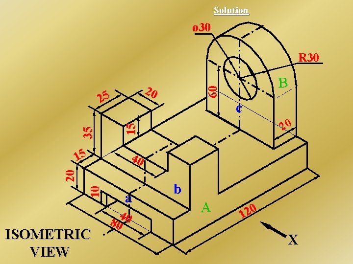
SOLUTION Isometric projection three dimensional objects in two
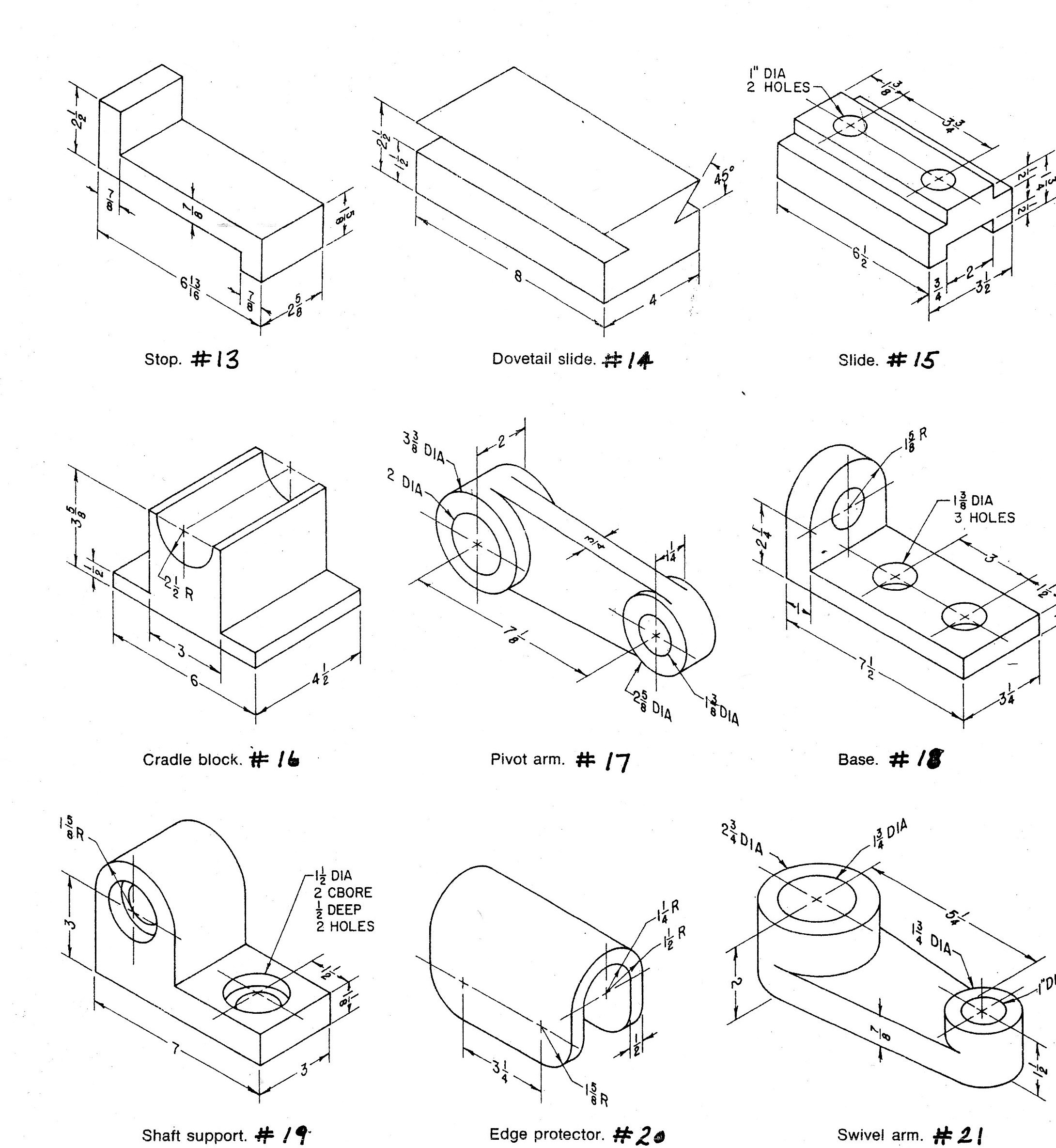
Draw a square d’ab’c od sides equal to the actual length of the edges of the cube with d’b’ as the common diagonal. Black = object line and hatching; If the isometric drawing can show all details and all dimensions on one drawing, it is ideal. A dimension listed on an engineering drawing is known as the _______ _______. Use.
Isometric Drawing With Dimensions
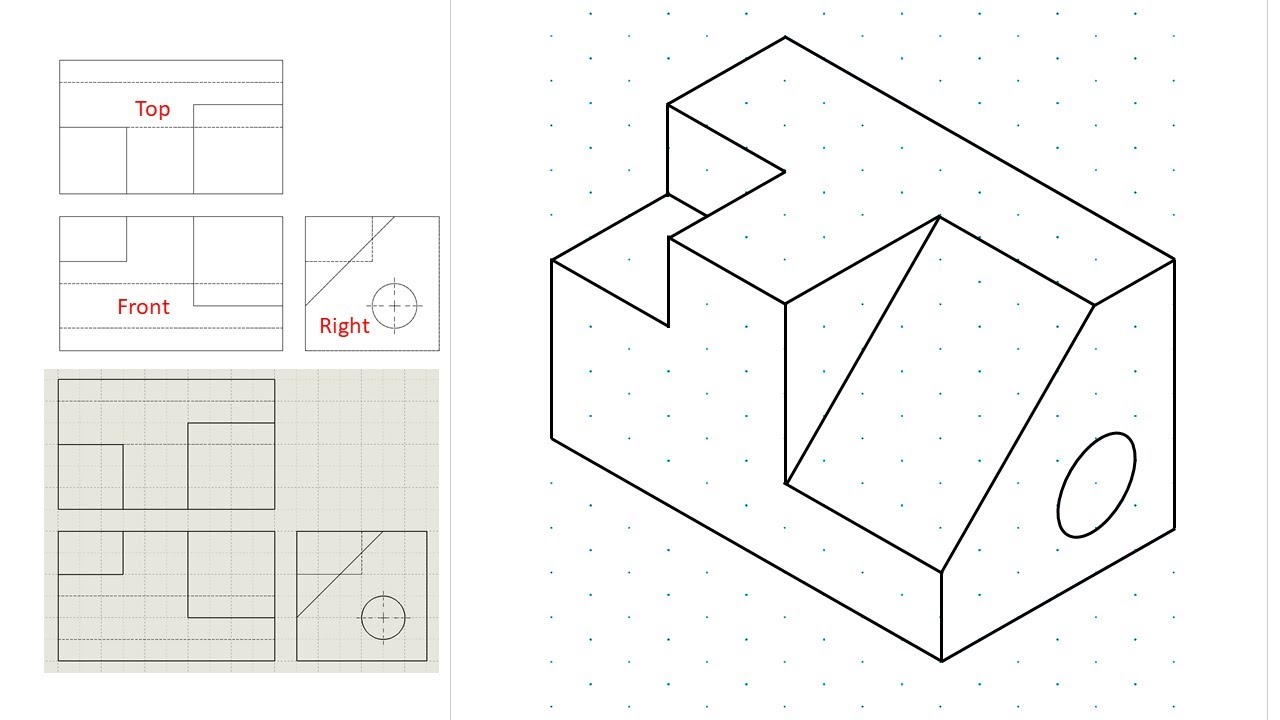
Start by clicking on the cube along the left side; In this comprehensive tutorial, we delve into the art of creating flawless isometric views using orthographic projecti. (in making an orthographic projection, any point in the object is mapped onto the drawing by dropping a perpendicular from that point to the plane of the drawing.) an isometric projection results if.

Isometric Drawing Basic Technical Drawing, 8th by Spencer, p. 138
Watch the video and learn the techniques of orthographic projections. Here is an example of an engineering drawing (an isometric view of the same object is shown above). They are used by architects and engineers to communicate their ideas to the client and manufacturer,. Web welcome back, engineering enthusiasts! Web isometric projection is a type of pictorial projection in which.

Isometric Views In Engineering Drawing
Then, place cubes on the grid where. Web isometric drawings are used to show a graphical representation of a 3d object. These drawings are particularly useful for conveying a clear understanding of how different parts of a structure fit together. The 3 axes that meet. This is due to the fact that the foreshortening of the axes is equal.
What is an Isometric Drawing? Types And Step To Draw
The angle the cube is tilted forward is 35. Web in this video, i have explained how to draw an isometric view of an object from an orthographic view. Isometric drawing, which is the same proportion as an isometric projection, but is larger by a. This is due to the fact that the foreshortening of the axes is equal. However,.
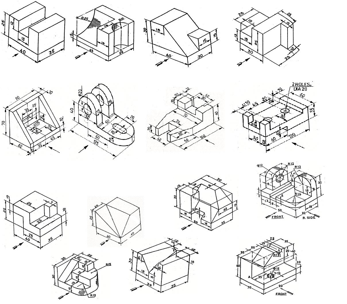
Isometric Drawing Engineering Exercises Pdf
They are used by architects and engineers to communicate their ideas to the client and manufacturer,. Web in this video, i have explained how to draw an isometric view of an object from an orthographic view. Here is an example of an engineering drawing (an isometric view of the same object is shown above). Web task 5.6 convert the orthographic.
Web In This Video, I Have Explained How To Draw An Isometric View Of An Object From An Orthographic View.
However, if the object in figure 2 had a hole on the back. Here is an example of an engineering drawing (an isometric view of the same object is shown above). It is an axonometric projection in which the three coordinate axes appear equally foreshortened and the angle between any two of them is 120 degrees. Start by clicking on the cube along the left side;
You Can Shift, Rotate, Color, Decompose, And View In 2‑D Or 3‑D.
D’c is the actual length of the edge, whereas corresponding edge d’c’ in the. Web learn to draw isometric projections using these simple steps provided. Web an isometric drawing is a 3d representation of an object, room, building or design on a 2d surface. Web isometric drawings are used to show a graphical representation of a 3d object.
Web The Isometric Is One Class Of Orthographic Projections.
Engineers may identify probable design defects, examine spatial linkages, and improve the overall aesthetic and performance of mechanical systems by visualizing complicated assemblies. Isometric drawings are easy once you learn the basic techniques. To find the extent to which the lengths of the edges are foreshortened. These drawings are particularly useful for conveying a clear understanding of how different parts of a structure fit together.
However, If The Object In Figure 2 Had A Hole On The Back.
Web any engineering drawing should show everything: This is due to the fact that the foreshortening of the axes is equal. In this comprehensive tutorial, we delve into the art of creating flawless isometric views using orthographic projecti. It is an axonometric projection in which the three coordinate axes appear equally foreshortened and the angle between any two of them is 120 degrees.