Isometric View In Engineering Drawing
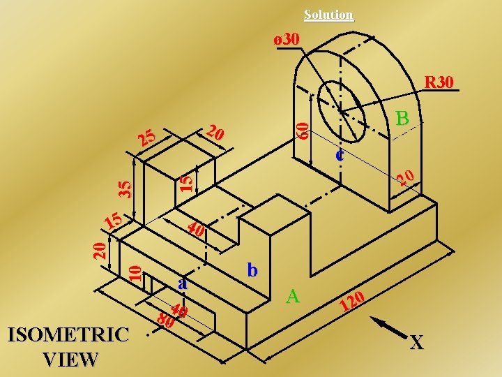
Isometric View In Engineering Drawing - Web the view drawn to the exact scale is known as the isometric view (isometric drawing). Web views are one of the important parameters in engineering drawings. Web task 5.6 convert the orthographic drawing shown below into an isometric drawings. Lengths are exact on isometric drawings only when the item is parallel to one of the axes of the drawing. If you draw this on paper, you may get. Also their actual sizes can be measured directly from the view., fig. 10 different types of lines used in engineering drawing. This is due to the fact that the foreshortening of the axes is equal. Web 4) consistency across views: Do not dimension the drawing.
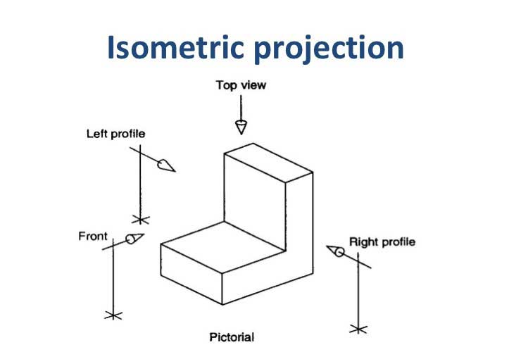
Watch the video and learn the techniques of orthographic projections. It is an axonometric projection in which the three coordinate axes appear equally foreshortened and the angle between any two of them is 120 degrees. Isometric drawings are a common language in technical. Web isometric views have no vanishing point, so the objects do not appear as they would in a perspective view. Lengths are exact on isometric drawings only when the item is parallel to one of the axes of the drawing. The purpose is to convey all the information necessary for manufacturing a product or a part. The 3 axes that meet. Categories engineering drawing tags dimension system, engineering drawing. Web the isometric is one class of orthographic projections. Web size comparison of isometric drawing and true isometric projection.
In this comprehensive tutorial, we delve into the art of creating flawless isometric views using orthographic projecti. (in making an orthographic projection, any point in the object is mapped onto the drawing by dropping a perpendicular from that point to the plane of the drawing.) an isometric projection results if the plane is oriented so that it makes equal angles (hence “isometric,” or “equal. One of the defining characteristics of an isometric drawing, compared to other types of 3d representation, is that the final image is not distorted and is always to scale. Web engineering drawing basics explained. 10 different types of lines used in engineering drawing. Web isometric views have no vanishing point, so the objects do not appear as they would in a perspective view. The 3 axes that meet. The representation of the object in figure 2 is called an isometric drawing. Isometric drawing, also called isometric. The purpose is to convey all the information necessary for manufacturing a product or a part.

Engineering Drawing Isometric Projections Example 3 YouTube
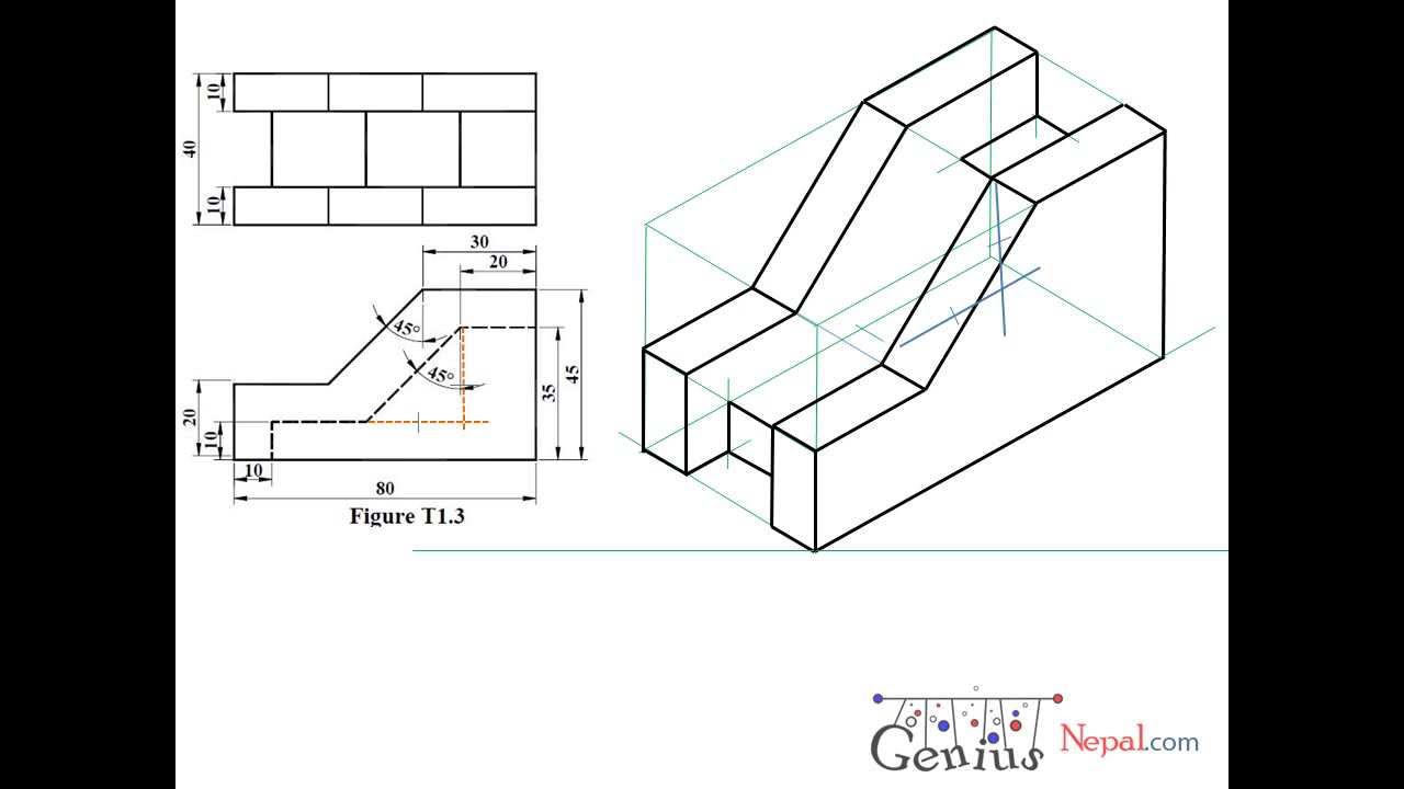
Web in this video, i have explained how to draw an isometric view of an object from an orthographic view. In this comprehensive tutorial, we delve into the art of creating flawless isometric views using orthographic projecti. The two main types of views (or “projections”) used in drawings are: Web the view drawn to the exact scale is known as.
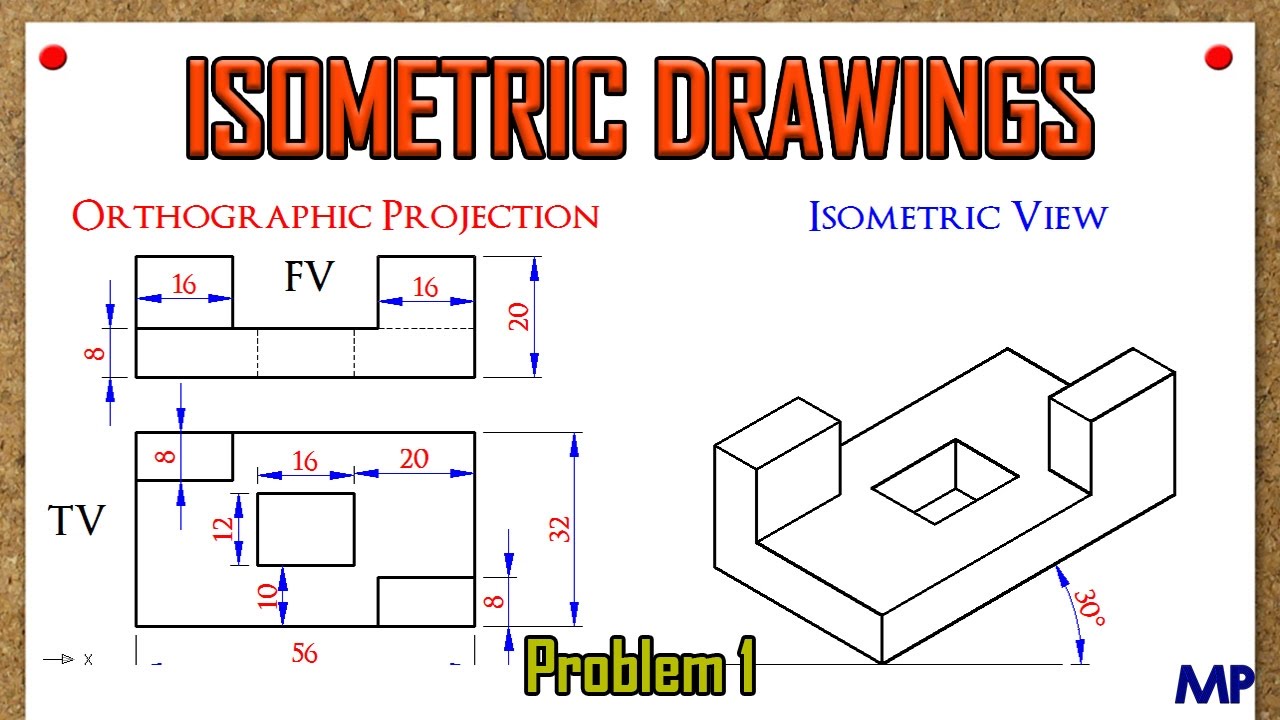
Isometric Views Problem 1 YouTube
The purpose is to convey all the information necessary for manufacturing a product or a part. Web views are one of the important parameters in engineering drawings. A dimension listed on an engineering drawing is known as the _______ _______. This makes understanding the drawings simple with little to no personal. Web discover how to draw amazing isometric views of.
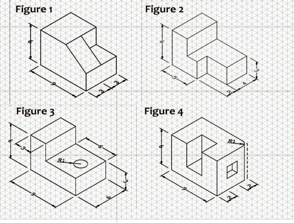
1.0 Orthographic Sketching Practice Jonesboro High School Engineering
Isometric drawings maintain consistency when representing the same object from different angles. Do not dimension the drawing. The purpose is to convey all the information necessary for manufacturing a product or a part. Web the view drawn to the exact scale is known as the isometric view (isometric drawing). An engineering drawing is a subcategory of technical drawings.
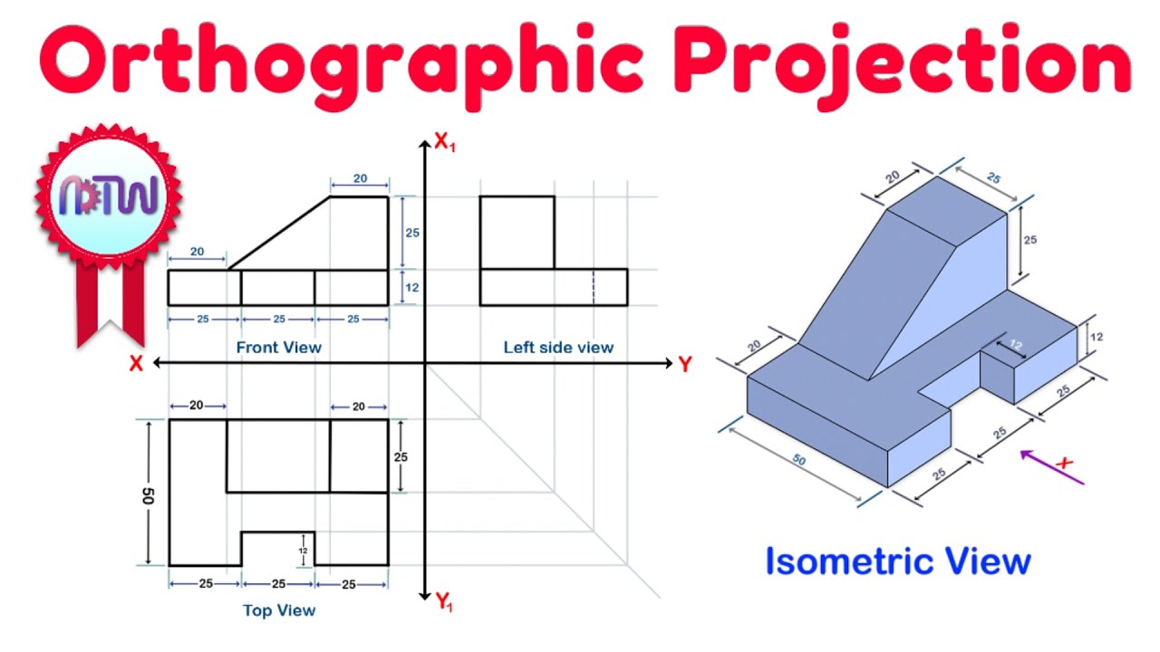
Orthographic Projection from isometric view in Engineering drawing
3d modelers often use orthographics to accurately create an object in a 3d application. Engineering drawings use standardised language and symbols. Views significantly contribute to how the overall design is understood. Web in this video, i have explained how to draw an isometric view of an object from an orthographic view. This makes understanding the drawings simple with little to.
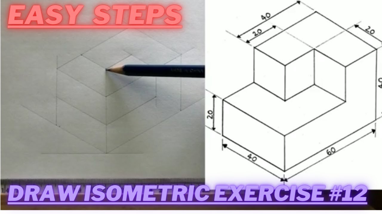
How to draw ISOMETRIC PROJECTIONS Technical Drawing Exercise 12
Based on the different types of views, the shape and size of the object/part are shown properly to the observer. Web size comparison of isometric drawing and true isometric projection. The angle the cube is tilted forward is 35. Chapter 4, isometric projections, 4.1 introduction, isometric projection is a type of pictorial projection in which all the three dimensions of.

Engineering Drawing Isometric Projections Example 2 YouTube
The purpose is to convey all the information necessary for manufacturing a product or a part. Due to the ease in construction and the advantage of measuring the dimensions directly from the. Web engineering drawing basics explained. Web task 5.6 convert the orthographic drawing shown below into an isometric drawings. Isometric drawings are easy once you learn the basic techniques.
Isometric Drawing, Projection Its Types, Methods.
Isometric drawings are easy once you learn the basic techniques. Web 4) consistency across views: All the edges of the cube are equally foreshortened , only bd is the true diagonal, bpdq is the true length top face of the cube. If you draw this on paper, you may get. Web discover how to draw amazing isometric views of objects.

Engineering Drawing Tutorials/Isometric drawing with front and side
Do not dimension the drawing. Web types of views used in drawings. Web task 5.6 convert the orthographic drawing shown below into an isometric drawings. Web the isometric is one class of orthographic projections. 10 different types of lines used in engineering drawing.
What is an Isometric Drawing? Types And Step To Draw
This is due to the fact that the foreshortening of the axes is equal. Watch the video and learn the techniques of orthographic projections. Web 4) consistency across views: Do not dimension the drawing. Lengths are exact on isometric drawings only when the item is parallel to one of the axes of the drawing.
Engineering Drawing Tutorials/Isometric drawing with front and side
More than likely, you will use a combination of these techniques while solving one problem. Based on the different types of views, the shape and size of the object/part are shown properly to the observer. While that drawn using the isometric scale is known as as the isometric projection. Chapter 4, isometric projections, 4.1 introduction, isometric projection is a type.
Figure 2 Shows An Isometric View Of A Simple Object, As Well As The Lines That Represent The Three Dimensions.
Web views are one of the important parameters in engineering drawings. The two main types of views (or “projections”) used in drawings are: (in making an orthographic projection, any point in the object is mapped onto the drawing by dropping a perpendicular from that point to the plane of the drawing.) an isometric projection results if the plane is oriented so that it makes equal angles (hence “isometric,” or “equal. Web learn to draw isometric projections using these simple steps provided.
It Is An Axonometric Projection In Which The Three Coordinate Axes Appear Equally Foreshortened And The Angle Between Any Two Of Them Is 120 Degrees.
Web in this video, i have explained how to draw an isometric view of an object from an orthographic view. While that drawn using the isometric scale is known as as the isometric projection. Due to the ease in construction and the advantage of measuring the dimensions directly from the. Views significantly contribute to how the overall design is understood.
Web Task 5.6 Convert The Orthographic Drawing Shown Below Into An Isometric Drawings.
It is an axonometric projection in which the three coordinate axes appear equally foreshortened and the angle between any two of them is 120 degrees. This makes understanding the drawings simple with little to no personal. In this comprehensive tutorial, we delve into the art of creating flawless isometric views using orthographic projecti. Isometric drawings are a common language in technical.
There Are Three Types Of Pictorial Views:
More than likely, you will use a combination of these techniques while solving one problem. 4.1 shows a cube standing on a corner g (o) with all the faces of the cube are. Also their actual sizes can be measured directly from the view., fig. Engineering drawings use standardised language and symbols.