Leader Line In Engineering Drawing
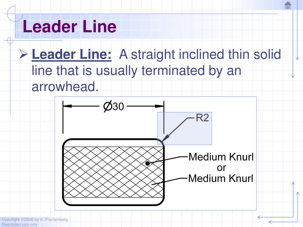
Leader Line In Engineering Drawing - Web the typical leads used are h, 2h, 4h (2 mm), and/or 0.03 mm, 0.05 mm, 0.07 mm, and 0.09 mm. These lines are solid and has no break in them. Leaders are used to indicate information about hole diameters, radii, and other information that occurs as a specific location or on a particular surface on the. Leader lines are straight or curved lines that have an arrow or dot at one end and are used to point to specific features or annotations in a drawing. Leader lines represent dimension values in drawings. They are often drawn at an angle or. Web a leader line is a line that establishes a connection between a graphical representation of an item and some text. Web there are 12 types of lines usually used in engineering drawing. A leader points to a bit of our drawing and says: In order to convey that.
The purpose of this guide is. The effective communication of design intent is. These are thin continuous lines drawn from a dimension figure to the feature to which it refers. Web leader lines, how they are used on blueprints. Web the continuous thin line is the most frequently used line type on engineering drawings. A leader points to a bit of our drawing and says: It is used to clarify the meaning of. This is especially true for the engineer. Leader lines represent dimension values in drawings. Line weight on a drawing varies from a thin line to a thicker line.
Line weight on a drawing varies from a thin line to a thicker line. Here is the list of cases where the. In order to convey that. Web engineering lines are graphical representations used in technical drawings to communicate information about the shape, size, and features of objects. Web dimension appearance and technique. It is one of the standard line. Web leader lines, how they are used on blueprints. Web leader lines are drawn as straight lines (but not horizontal or vertical) that originate from a specific location and end with an arrowhead or a dot. A leader points to a bit of our drawing and says: Leaders are used to indicate information about hole diameters, radii, and other information that occurs as a specific location or on a particular surface on the.

What are Lines & Types Of Lines in Engineering Drawing ? YouTube
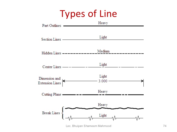
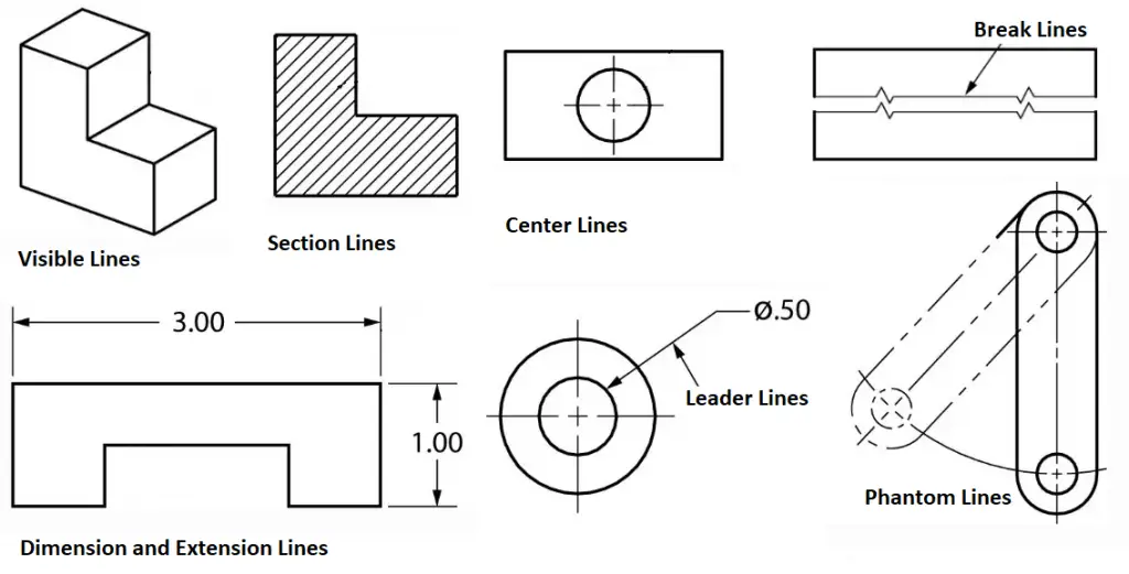
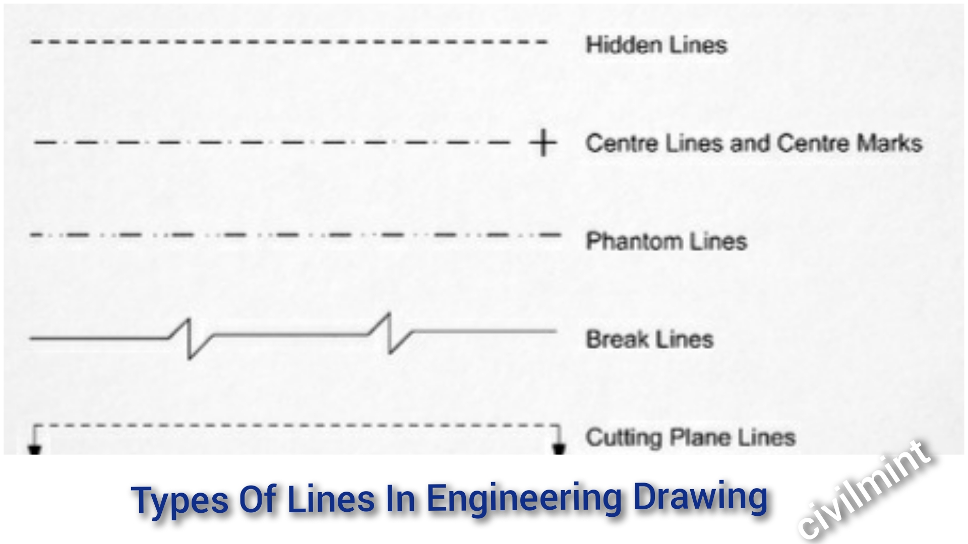
Web there are 12 types of lines usually used in engineering drawing. To properly read and interpret drawings, you must know the meaning of each line and understand how each is used to construct a drawing. A leader points to a bit of our drawing and says: Leaders are more thin lines used to point to an area of a.
PPT Chapter 2 Dimensioning PowerPoint Presentation, free download
This is especially true for the engineer. Leaders are used to indicate information about hole diameters, radii, and other information that occurs as a specific location or on a particular surface on the. The effective communication of design intent is. Web a leader line is a line that establishes a connection between a graphical representation of an item and some.

leader line in engineering drawing howtobetteryourselfeveryday
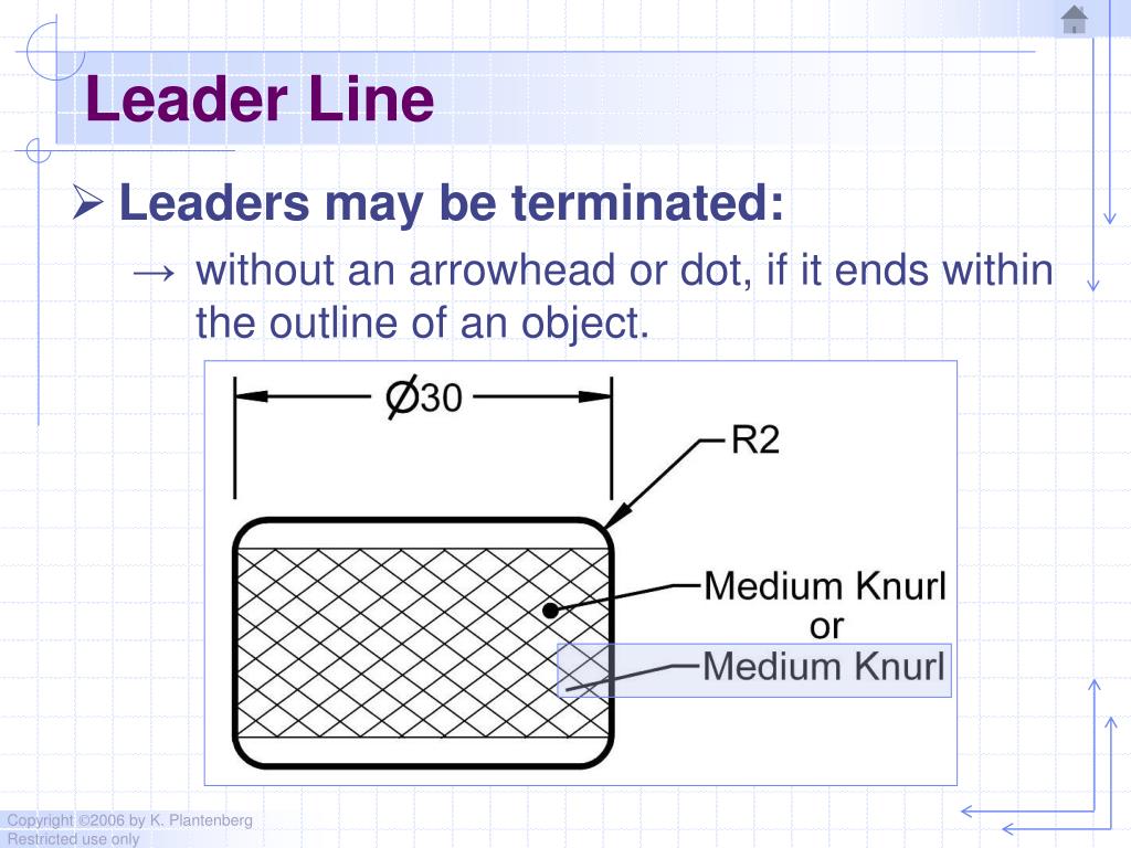
Web leader lines are fine lines terminating with an arrowhead or dot at one end to relate a note or callout to its feature. Web the typical leads used are h, 2h, 4h (2 mm), and/or 0.03 mm, 0.05 mm, 0.07 mm, and 0.09 mm. It is one of the standard line. Leaders are used to indicate information about hole.
Engineering Drawing 8 Tips to Improve Engineering Drawing Skills
Dimensions use special lines, arrows, symbols and text. One of the best ways to communicate one’s ideas is through some form of picture or drawing. A leader points to a bit of our drawing and says: Web dimension appearance and technique. Standard lines have been developed so that every drawing or sketch conveys the same meaning to everyone.

Engineering Drawing Dimensioning Part 1 YouTube
One of the best ways to communicate one’s ideas is through some form of picture or drawing. Web dimension appearance and technique. Leaders are used to indicate information about hole diameters, radii, and other information that occurs as a specific location or on a particular surface on the. It is one of the standard line. These are thin continuous lines.
PPT ENGINEERING DRAWING PowerPoint Presentation, free download ID
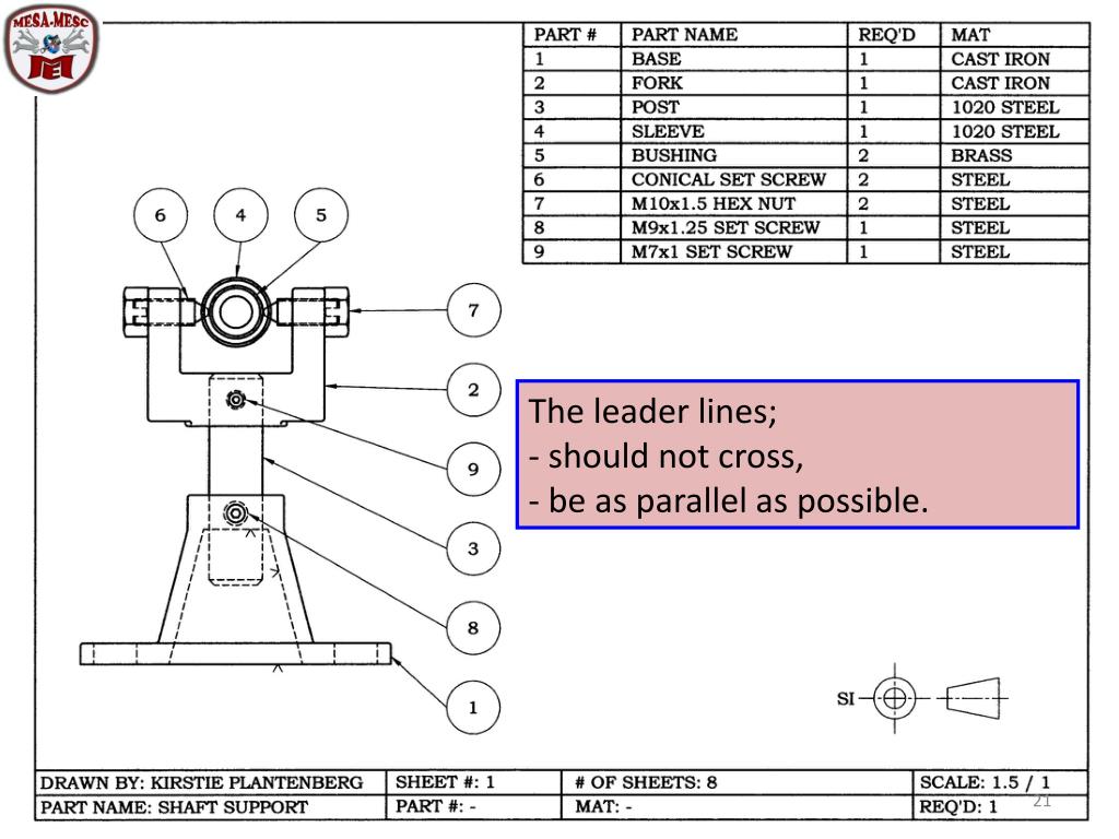
The extension lines for dimensioning should run from the outlines without leaving a gap. Leaders are more thin lines used to point to an area of a drawing requiring a note for explanation. Leader lines are straight or curved lines that have an arrow or dot at one end and are used to point to specific features or annotations in.
Types of Lines in Engineering Drawing (PDF) What Is Piping
Leaders are used to indicate information about hole diameters, radii, and other information that occurs as a specific location or on a particular surface on the. The extension lines for dimensioning should run from the outlines without leaving a gap. They are often drawn at an angle or. A short horizontal portion should extend to the first or last letter.
PPT Chapter 2 Dimensioning PowerPoint Presentation, free download
Web leader lines, how they are used on blueprints. They are often drawn at an angle or. To properly read and interpret drawings, you must know the meaning of each line and understand how each is used to construct a drawing. Web dimension appearance and technique. Leaders are more thin lines used to point to an area of a drawing.
Types Of Lines In Engineering Drawing
The effective communication of design intent is. Leaders are more thin lines used to point to an area of a drawing requiring a note for explanation. Web the typical leads used are h, 2h, 4h (2 mm), and/or 0.03 mm, 0.05 mm, 0.07 mm, and 0.09 mm. In the realm of engineering and architecture, precision and clarity are paramount. This.

Types of Lines Engineering Drawing MechGate YouTube
Web the continuous thin line is the most frequently used line type on engineering drawings. These lines are solid and has no break in them. Web there are 12 types of lines usually used in engineering drawing. Leaders are more thin lines used to point to an area of a drawing requiring a note for explanation. The proportions between the.
Web The Typical Leads Used Are H, 2H, 4H (2 Mm), And/Or 0.03 Mm, 0.05 Mm, 0.07 Mm, And 0.09 Mm.
Web dimension, projection, leader, hatching type lines must be drawn thin and continuous. Web 5 line widths and line groups on mechanical engineering drawings, two line widths are normally used. The arrowhead or dot indicates the precise. Leader lines represent dimension values in drawings.
These Lines Are Solid And Has No Break In Them.
A short horizontal portion should extend to the first or last letter of the note. This is especially true for the engineer. The extension lines for dimensioning should run from the outlines without leaving a gap. Leader lines are straight or curved lines that have an arrow or dot at one end and are used to point to specific features or annotations in a drawing.
To Properly Read And Interpret Drawings, You Must Know The Meaning Of Each Line And Understand How Each Is Used To Construct A Drawing.
Leaders are more thin lines used to point to an area of a drawing requiring a note for explanation. The proportions between the line widths should be 1:2. A leader points to a bit of our drawing and says: Dimensions make use of dimension lines, extension.
Web Dimension Appearance And Technique.
Web leader lines, how they are used on blueprints. The effective communication of design intent is. Dimensions use special lines, arrows, symbols and text. Web a leader line is a thin, solid line with an arrow drawn under an angle, indicating the feature with which a dimension or note is associated.