Loop Drawing
Loop Drawing - We talk about what they are, how th. List of link for free instrumentation loop generator tool. Loop diagrams are fairly constrained in their layout as per the isa 5.1 standard. What is an instrument loop folder? Instrument loop drawings from tabulated excel data; Is there a way to make diagrams and flowcharts in microsoft loop? Created on may 31, 2023. From an installation and maintenance electrician’s point of view, two of the most useful types of drawings that can be included in a contract drawing set are loop diagrams and process loop sheets. Loop diagrams can be customized or edited as per service requirements. Web loop diagram shows instrument (in a symbol) and its terminal numbers which are to be connected, instrument cable number, junction box number, terminal number assigned for the specified.
Web this is a video that describes in detail how to read an instrument loop diagram. Web p&ids and loop diagrams are construction and documentation drawings that depict the flow of the process and illustrate the instrumentation control and measurement interactions, wiring and connections to the process. Web loop diagram shows instrument (in a symbol) and its terminal numbers which are to be connected, instrument cable number, junction box number, terminal number assigned for the specified. Free instrumentation loop drawing generator; Make a causal loop diagram. We talk about what they are, how th. List of link for free instrumentation loop generator tool. Web loop drawing are mostly drawn on drafting software like autocad but nowadays they can be generated automatically by intelligent design data base softwares. We would like to try out loop for our company but we really miss the lack of creating diagrams and flow charts. It displays the detail of the loop by which it is helpful during the commissioning and maintenance activities.
We would like to try out loop for our company but we really miss the lack of creating diagrams and flow charts. Web loop diagram shows instrument (in a symbol) and its terminal numbers which are to be connected, instrument cable number, junction box number, terminal number assigned for the specified. Generation of instrument loop diagram ; I am not talking about making a diagram and adding it like a picture. A company logo can also be included in the output. Some useful questions related to loop drawings: (vice versa) instrument loop diagram is divided into two basic sections. What is loop number of an instrument? Web instrument loop diagram (ild) represents a connection from the field instrument to control room. Various types of loop diagrams:

18. Schematic drawing of two circular loops with center discs
Various types of loop diagrams: Created on may 31, 2023. Make a causal loop diagram. One is the field side and other is control room side. The process is illustrated in sections or subsystems of the process called loops.

c How to draw a loop shape in WPF? Stack Overflow
It displays the detail of the loop by which it is helpful during the commissioning and maintenance activities. 1.5k views 3 years ago. Generation of instrument loop diagram ; Web the loop diagram shows how the field input and output are used in the control system; We would like to try out loop for our company but we really miss.
An infinite loop drawing EASY HOW TO DRAW YouTube
Basically, instrument loop diagrams represents detailed drawing showing an instrument wiring connection. Web loop diagram shows instrument (in a symbol) and its terminal numbers which are to be connected, instrument cable number, junction box number, terminal number assigned for the specified. Fluid ports on instruments are also represented by labeled squares. A cover page and table to contents is included.
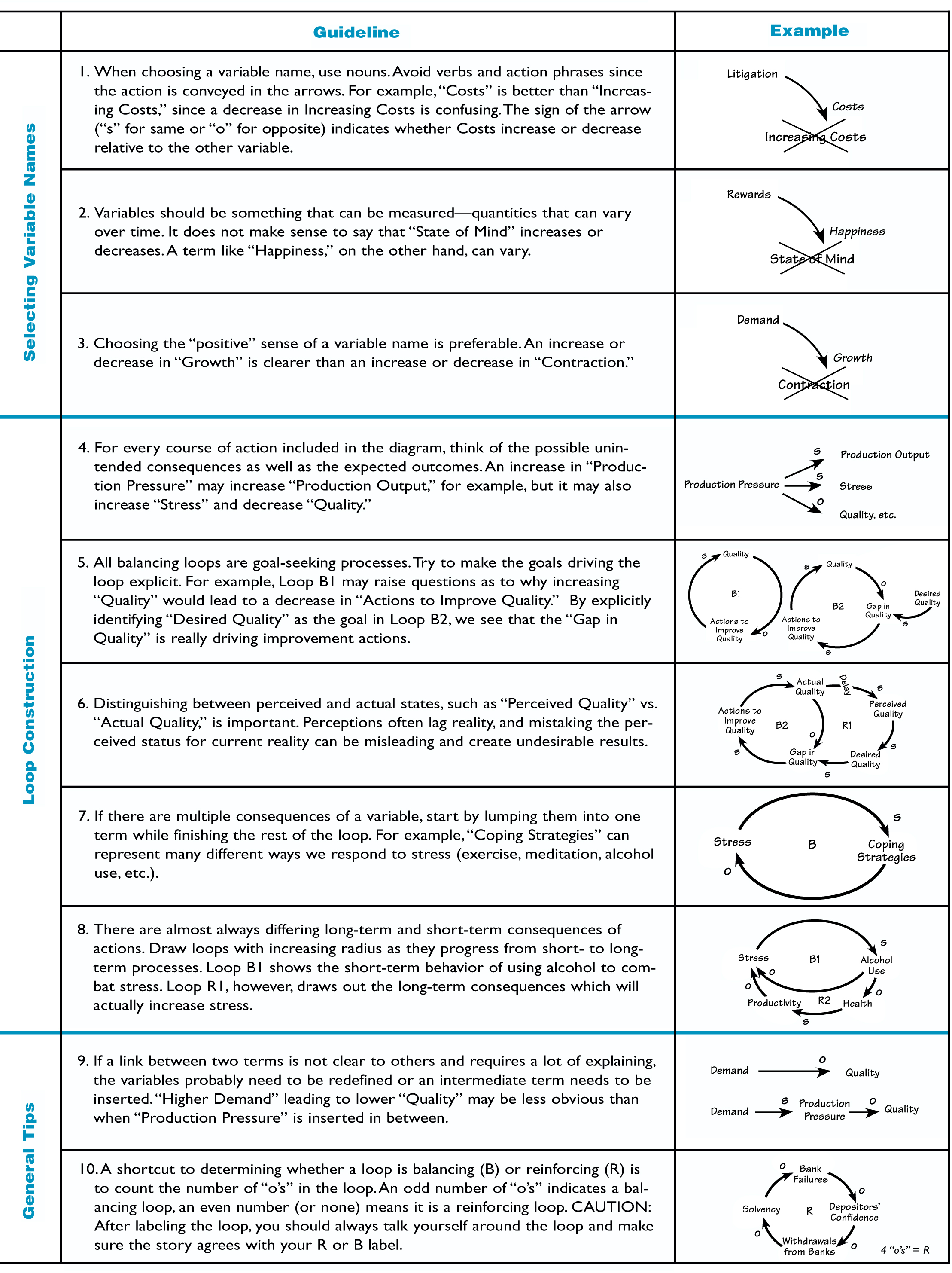
The Systems Thinker Guidelines for Drawing Causal Loop Diagrams The
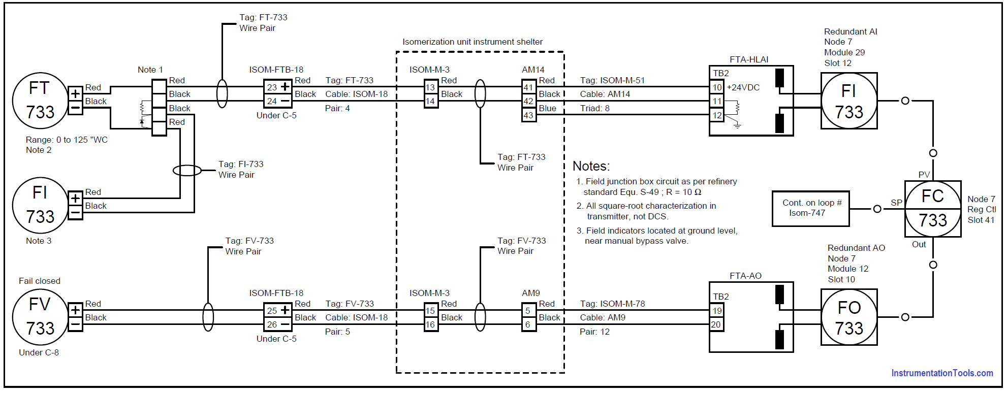
We would like to try out loop for our company but we really miss the lack of creating diagrams and flow charts. Created on may 31, 2023. Web when a loop diagram shows you exactly what wire color to expect at exactly what point in an instrumentation system, and exactly what terminal that wire should connect to, it becomes much.

4 wire loop drawings explained Learn Instrumentation Engineering
Vp online features a powerful causal loop diagram tool that lets you create causal loop diagram easily and quickly. Web by john robert davis and graham nasby. The tool can generate 2 wire or 4 wire drawings. In other words, an instrument loop diagram is also known as instrument. List of link for free instrumentation loop generator tool.

How to Draw a Loop De Loop Drawing Part 2 YouTube
Purpose of this particular instrumentation design deliverable is but not limited to : How to read/interpret a loop diagram? Web a loop diagram is the diagrammatic representation or a graphical sketch of a control system with a process flow diagram and respective piping and instrument diagrams in detail. A company logo can also be included in the output. Generation of.
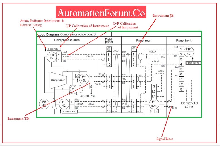
Howto Create Instrument Loop Diagram (ILD)? AutomationForum
Web the loop diagram shows how the field input and output are used in the control system; Web this is a video that describes in detail how to read an instrument loop diagram. Web p&ids and loop diagrams are construction and documentation drawings that depict the flow of the process and illustrate the instrumentation control and measurement interactions, wiring and.
15 Loop Diagram Questions Instrumentation Tools
I am not talking about making a diagram and adding it like a picture. It displays the detail of the loop by which it is helpful during the commissioning and maintenance activities. This is useful in teaching instrumentation technicians and drafters. A company logo can also be included in the output. How to create instrument loop drawing?

The problem solving loop drawing free image download
1.5k views 3 years ago. Some useful questions related to loop drawings: Web process and instrument diagrams (p&ids), also called piping and instrumentation diagrams and loop diagrams are construction and documentation drawings that show the flow of the process and illustrate the instrumentation control and measurement instructions, wiring and connections to the process. A draw.io plugin would also be a.
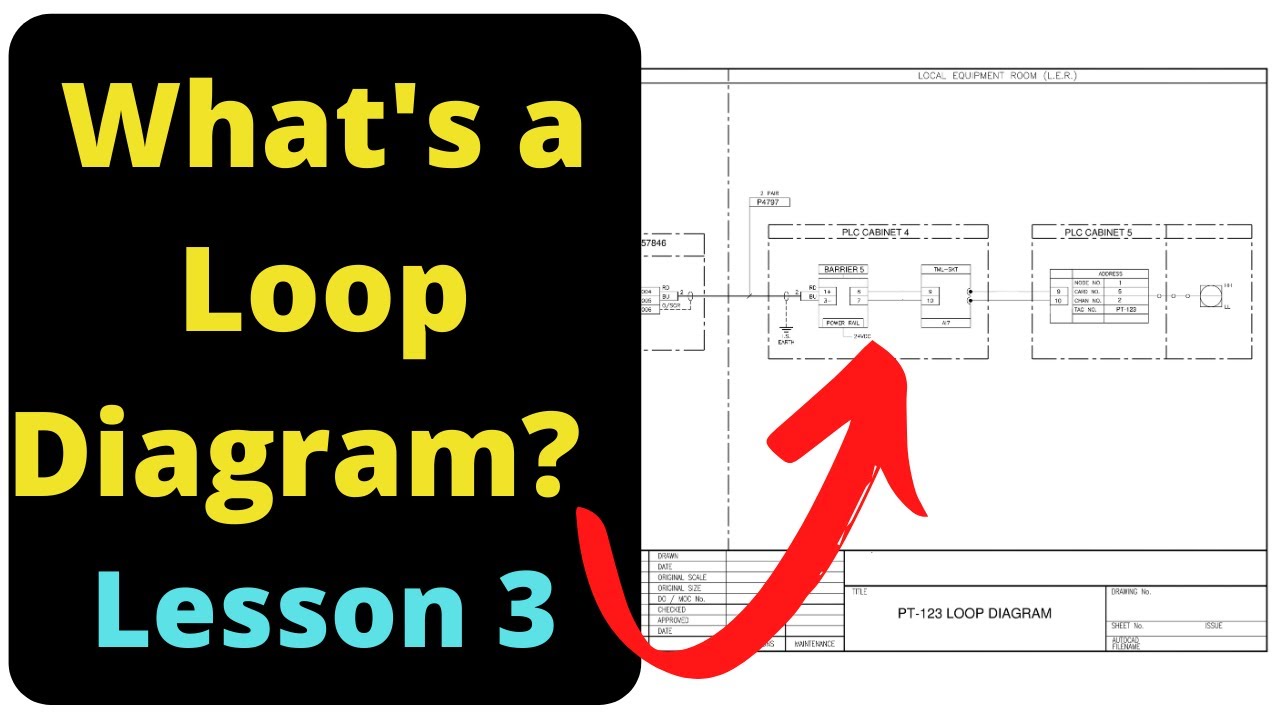
What is a Loop Diagram Instrumentation Course Lesson 3 YouTube
Generation of instrument loop diagram ; The process is illustrated in sections or subsystems of the process called loops. Web loop diagrams are the most detailed form of diagrams for a control system and thus it must contain all details omitted by pfds and p&ids alike. Make a causal loop diagram. Web electrical terminals where these wires connect to are.
Generation Of Instrument Loop Diagram ;
Web a loop diagram is the diagrammatic representation or a graphical sketch of a control system with a process flow diagram and respective piping and instrument diagrams in detail. (vice versa) fieldside is again divided into field area and junction box. (vice versa) instrument loop diagram is divided into two basic sections. The tool can generate 2 wire or 4 wire drawings.
It Illustrates The Interconnections And Interactions Between Various Instruments, Devices, And Components Within The Control System.
Understanding loop diagrams and process loop sheets. Web this is a video that describes in detail how to read an instrument loop diagram. Web when a loop diagram shows you exactly what wire color to expect at exactly what point in an instrumentation system, and exactly what terminal that wire should connect to, it becomes much easier to proceed with any troubleshooting, calibration, or upgrade task. Web electrical terminals where these wires connect to are represented by squares with numbers in them.
Make A Causal Loop Diagram.
1) showing how the control system is getting instruments data and how it controlling output. Fluid ports on instruments are also represented by labeled squares. Web this video shows the basics of loop diagram.course link: How to read/interpret a loop diagram?
A Company Logo Can Also Be Included In The Output.
Web loop drawing are mostly drawn on drafting software like autocad but nowadays they can be generated automatically by intelligent design data base softwares. Basically, instrument loop diagrams represents detailed drawing showing an instrument wiring connection. Web the loop diagram is the document consist of all connections of instruments from the field to the control panel. Web by john robert davis and graham nasby.