Motor Schematic Drawing
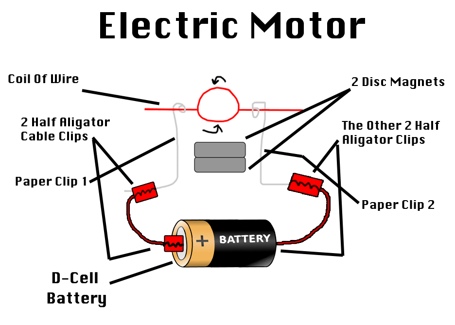
Motor Schematic Drawing - Web motor wiring diagrams are essential tools for understanding and troubleshooting the electrical connections in motors. Web anatomy of a dc motor: A simplified diagram of the parts in an electric motor. Web a typical electric motor diagram includes components such as the power source, which can be a battery or an electrical outlet, the motor itself, and any additional devices like. Motor contactor (or “starter”) coils are typically designated by the letter “m” in ladder logic diagrams. To understand how an electric motor works, the key is to understand how the electromagnet works. The design provides a comprehensive. Web thermal protectors can also be built into the windings, see the illustration below. (see how electromagnets work for complete. Web a typical wiring diagram for a single phase motor includes several components, such as the power supply, starting and running capacitors, and the motor itself.
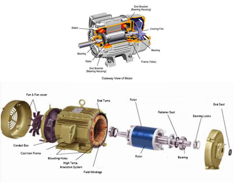
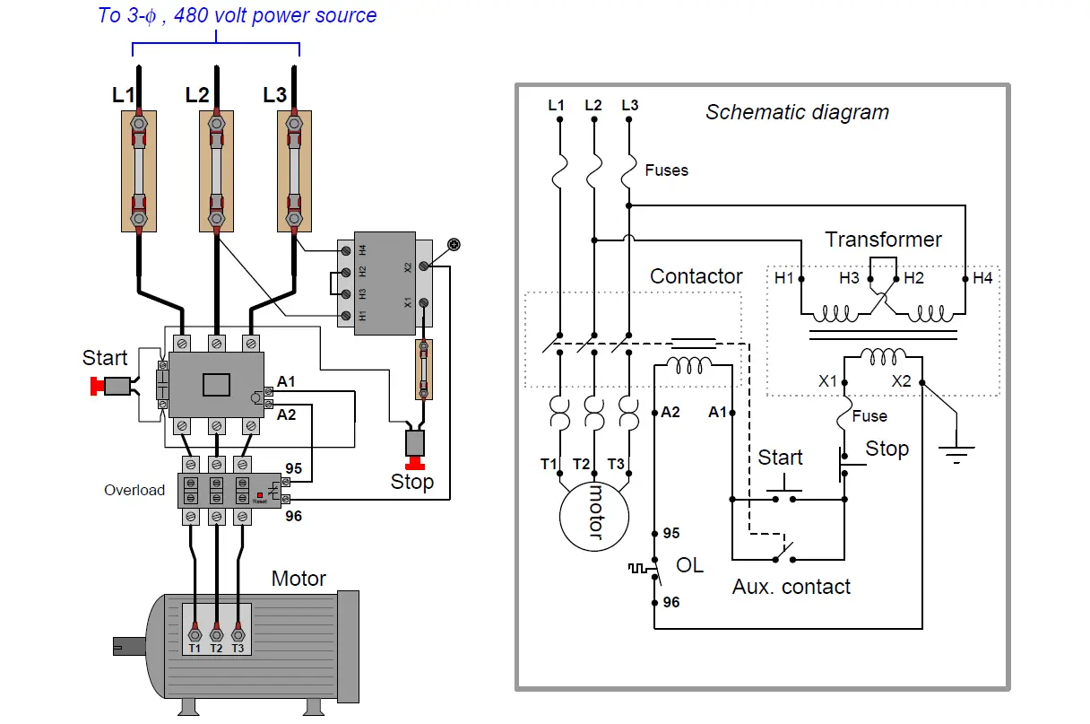
Web a typical electric motor diagram includes components such as the power source, which can be a battery or an electrical outlet, the motor itself, and any additional devices like. Web motor wiring diagrams are essential tools for understanding and troubleshooting the electrical connections in motors. Three phase motor connection schematic, power and control wiring installation diagrams. How it works in practice. Web these diagrams provide a visual representation of the motor’s electrical circuit, allowing engineers and technicians to analyze and troubleshoot any issues that may arise. They provide a visual representation of how the different. Web anatomy of a dc motor: Web thermal protectors can also be built into the windings, see the illustration below. An electric motor is a machine that converts electrical energy to mechanical energy. Web welcome to module 16, which is about the basics of motors and motor control.
Continuous motor operation with a momentary “start” switch is. A dc motor is an electrical device that converts direct current (dc) electrical energy into mechanical energy. A simplified diagram of the parts in an electric motor. Web by studying the schematic diagram of an electric motor, one can gain a deeper understanding of how the various components work together to produce rotational. Three phase motor power & control wiring diagrams. Web motor wiring diagrams are essential tools for understanding and troubleshooting the electrical connections in motors. How it works in practice. Web a typical wiring diagram for a single phase motor includes several components, such as the power supply, starting and running capacitors, and the motor itself. Web 23 1 minute read. Web a typical electric motor diagram includes components such as the power source, which can be a battery or an electrical outlet, the motor itself, and any additional devices like.

Schematic View of a Steam Engine Download Scientific Diagram
Web january 4, 2021 by electrical4u. A dc motor is an electrical device that converts direct current (dc) electrical energy into mechanical energy. An electric motor is a machine that converts electrical energy to mechanical energy. They provide a visual representation of how the different. Three phase motor connection schematic, power and control wiring installation diagrams.
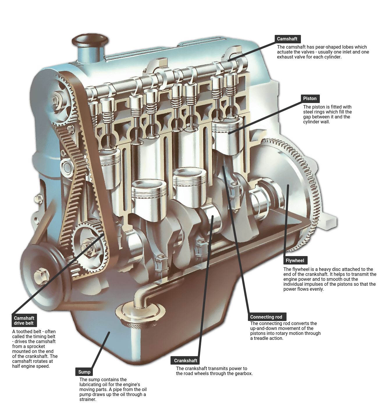
Diagram Car Motor
A dc motor is an electrical device that converts direct current (dc) electrical energy into mechanical energy. Web a typical wiring diagram for a single phase motor includes several components, such as the power supply, starting and running capacitors, and the motor itself. (see how electromagnets work for complete. Dc motors are widely used in various applications,. Web a typical.
Electric Motor Diagram by TheDevinGreat on DeviantArt
Web anatomy of a dc motor: Web a dc motor wiring schematic is a diagram that shows how to connect the various components of a dc motor together. To understand how an electric motor works, the key is to understand how the electromagnet works. (see how electromagnets work for complete. Web motor wiring diagrams are essential tools for understanding and.

Schematic diagram of the cylinder and the piston in an engine
They provide a visual representation of how the different. Web january 4, 2021 by electrical4u. Web these diagrams provide a visual representation of the motor’s electrical circuit, allowing engineers and technicians to analyze and troubleshoot any issues that may arise. A simplified diagram of the parts in an electric motor. Web 23 1 minute read.
Electric Motor Diagram Parts
A dc motor is an electrical device that converts direct current (dc) electrical energy into mechanical energy. Web by studying the schematic diagram of an electric motor, one can gain a deeper understanding of how the various components work together to produce rotational. Web anatomy of a dc motor: Web motor wiring diagrams are essential tools for understanding and troubleshooting.

Dc Motor Circuit Diagram
Web january 4, 2021 by electrical4u. Web 23 1 minute read. The design provides a comprehensive. An electric motor is a machine that converts electrical energy to mechanical energy. A simplified diagram of the parts in an electric motor.
Circuit Diagram Of Motor
Web welcome to module 16, which is about the basics of motors and motor control. Three phase motor connection schematic, power and control wiring installation diagrams. Continuous motor operation with a momentary “start” switch is. Web anatomy of a dc motor: The design provides a comprehensive.
![[Get 19+] Draw The Schematic Diagram Of An Electric Motor And Label It](https://www.vedantu.com/question-sets/4b50ccd0-6ff4-4582-a1a7-79edded35e117630552837600062191.png)
[Get 19+] Draw The Schematic Diagram Of An Electric Motor And Label It
A dc motor is an electrical device that converts direct current (dc) electrical energy into mechanical energy. Continuous motor operation with a momentary “start” switch is. They provide a visual representation of how the different. An electric motor is a machine that converts electrical energy to mechanical energy. Web thermal protectors can also be built into the windings, see the.
Simple Motor Control Circuit Diagram
Motor contactor (or “starter”) coils are typically designated by the letter “m” in ladder logic diagrams. Web motor wiring diagrams are essential tools for understanding and troubleshooting the electrical connections in motors. How it works in practice. Continuous motor operation with a momentary “start” switch is. A stepper motor driver (or stepper motor drive) is a circuit used to drive.

Single Phase Motor Schematic Diagram
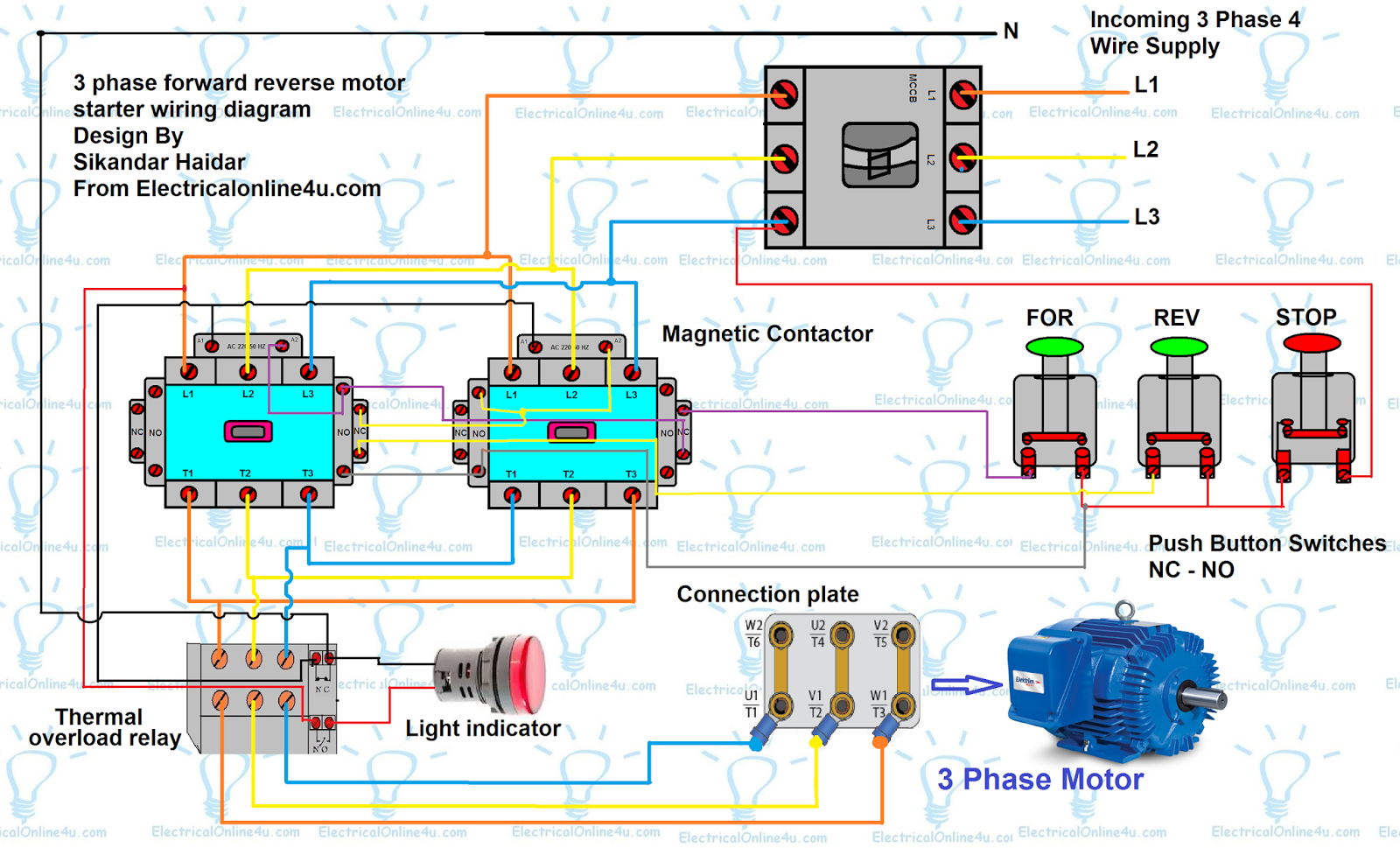
Web this diagram shows how the three phases are connected to the motor’s terminals, and it also includes information on how to connect the motor to the power source and control. Web a typical wiring diagram for a single phase motor includes several components, such as the power supply, starting and running capacitors, and the motor itself. Web this autocad.
Web A Typical Wiring Diagram For A Single Phase Motor Includes Several Components, Such As The Power Supply, Starting And Running Capacitors, And The Motor Itself.
The design provides a comprehensive. Web this autocad drawing showcases a meticulously detailed electric motor, with both plan and elevation views presented in a 2d format. Web thermal protectors can also be built into the windings, see the illustration below. (see how electromagnets work for complete.
Dc Motors Are Widely Used In Various Applications,.
Continuous motor operation with a momentary “start” switch is. Three phase motor connection schematic, power and control wiring installation diagrams. Web a typical electric motor diagram includes components such as the power source, which can be a battery or an electrical outlet, the motor itself, and any additional devices like. They provide a visual representation of how the different.
A Stepper Motor Driver (Or Stepper Motor Drive) Is A Circuit Used To Drive Or Run A Stepper.
What is a stepper motor driver? Web january 4, 2021 by electrical4u. Web this diagram shows how the three phases are connected to the motor’s terminals, and it also includes information on how to connect the motor to the power source and control. Web motor wiring diagrams are essential tools for understanding and troubleshooting the electrical connections in motors.
Three Phase Motor Power & Control Wiring Diagrams.
An electric motor is a machine that converts electrical energy to mechanical energy. Web these diagrams provide a visual representation of the motor’s electrical circuit, allowing engineers and technicians to analyze and troubleshoot any issues that may arise. A simplified diagram of the parts in an electric motor. How it works in practice.