Parallel Circuit Drawing
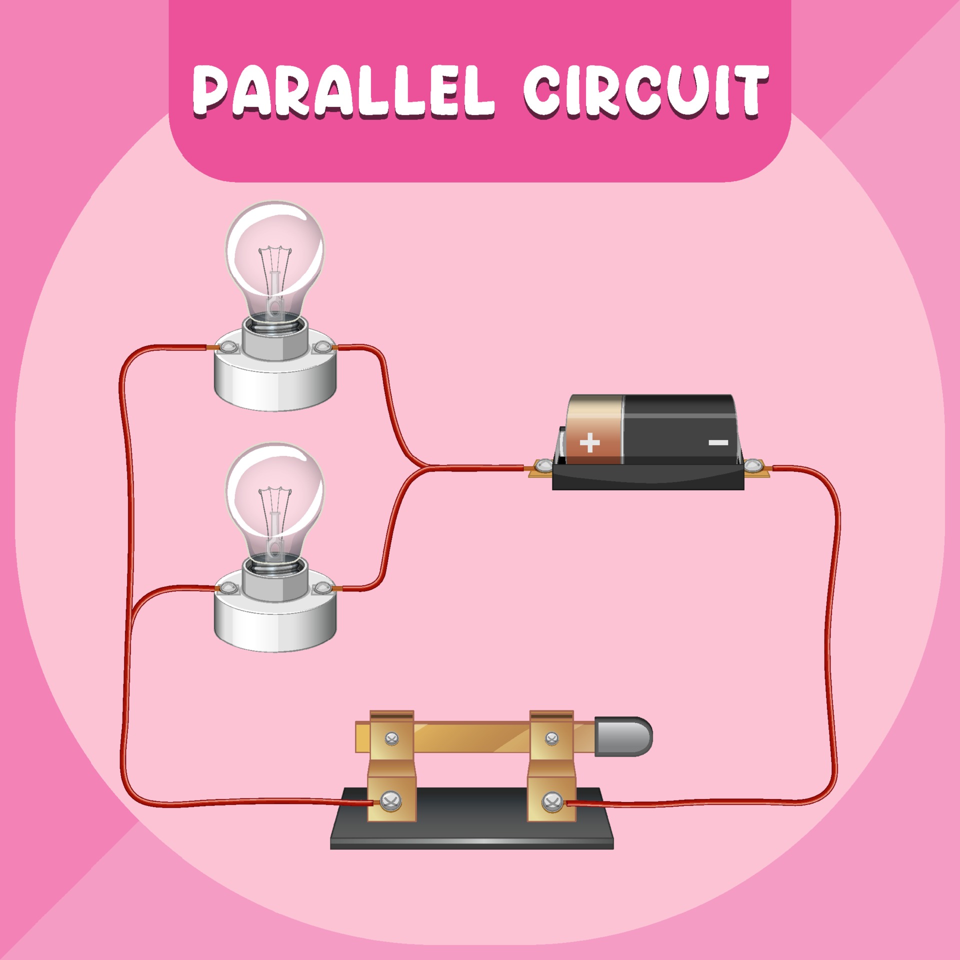
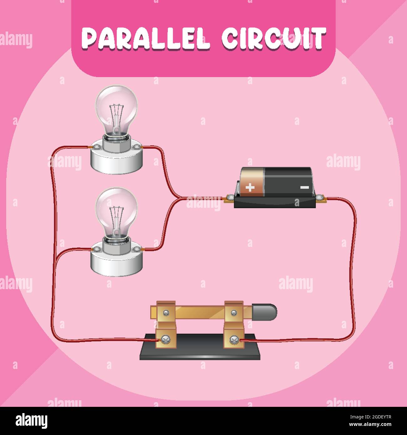
Parallel Circuit Drawing - It allows them to easily identify the components of a given circuit, allowing for more accurate troubleshooting, optimization, and design. 1 shows a parallel circuit consisting of three resistances r 1, r 2 and r 3 connected in parallel across a source of potential difference v volts and drawing a total current of i amperes. Add a second cell in series with the first cell. Web the total circuit power is additive for series, parallel, or any combination of series and parallel components. This guide will take you through the steps for creating a parallel circuit diagram, helping you better. Diagram a displays two resistors in parallel with nodes at point a and point b. The voltage is equal across all components in a parallel circuit.; A circuit diagram composed of a battery and three resistors demonstrating series and parallel circuit. Web then, draw a circuit with several components on the board (see figure 3 for an example sketch). They should be narrow, about the width of a drinking straw.
Web the total circuit power is additive for series, parallel, or any combination of series and parallel components. For instance, if the above circuit were simple series, we could just add up r 1 through r 4 to arrive at a total. We will apply this in the above circuit. The resistors r3 and r4 are in series and the equivalent resistance is r34 = 10ω (c) step 2: Web then, draw a circuit with several components on the board (see figure 3 for an example sketch). Let i 1, i 2 and i 3 be the currents in the resistances r 1, r 2 and r 3 respectively. Web a parallel circuit is a circuit that is connected entirely in parallel. Web to find total resistance r t across the circuit, solve for it in the equation 1 / rt = 1 / r1 + 1 / r2 + 1 / r3 +. 1/r t =1/r 1 +1/r 2 +1/r 3. The long line denotes the positive side, while the short line.
(a) the original circuit of four resistors. This is usually represented by a long and a short line parallel to each other. Web drawing a parallel circuit diagram is an essential skill for any electrical engineer or technician. To recognize a parallel circuit, to distinguish it from a series circuit, and to construct and/or interpret a schematic diagram of a parallel circuit. Add a second cell in series with the first cell. Web to find total resistance r t across the circuit, solve for it in the equation 1 / rt = 1 / r1 + 1 / r2 + 1 / r3 +. We will apply this in the above circuit. Web the right circuit diagram shows an equivalent resistance that replaces the three parallel resistors. Ask the class to identify which components of the circuit are connected in series and which are connected in parallel. Construct a series circuit with 1 cell, a resistor and the ammeter in series in the phet simulation.
How To Calculate A Series Parallel Circuit Wiring View and Schematics
A circuit diagram composed of a battery and three resistors demonstrating series and parallel circuit. Two components are in series if they. [4] for example, a circuit has two resistors in parallel, each with 4ω resistance. The total resistance of a parallel circuit is less than any of the. Web here, we note the equivalent resistance as req.
Parallel Circuit Vector Art, Icons, and Graphics for Free Download
(a) the original circuit of four resistors. Web prepare your conductors. Web parallel circuit, an electrical path that branches so that the current divides and only part of it flows through any branch. Again, we have three resistors, but this time there are three loops for the current to flow from the positive battery terminal back to the negative terminal:.

Parallel electrical circuit. parallel diagram of a circuit Stock Vector
That's the key difference between series and parallel!. Here are some tips for reading these diagrams: Examine the example circuit, below. Web here, we note the equivalent resistance as req. Let i 1, i 2 and i 3 be the currents in the resistances r 1, r 2 and r 3 respectively.
Figure 3 SeriesParallel Circuit 2 Electrical Academia
The total circuit current equals the sum of the individual branch currents.; The voltage, or potential difference, across each branch of a parallel circuit is the same, but the currents may vary. Web then, draw a circuit with several components on the board (see figure 3 for an example sketch). [4] for example, a circuit has two resistors in parallel,.

Parallel Circuit With Switch
Let i 1, i 2 and i 3 be the currents in the resistances r 1, r 2 and r 3 respectively. That's the key difference between series and parallel!. When calculating the power dissipation of resistive components, we can use any one of the three ohm’s law power equations if given any two of the voltage (v), current (i).

How to Make a Parallel Circuit (with Pictures) wikiHow
This is usually represented by a long and a short line parallel to each other. Answer the same questions as in #1. Web in this introduction to parallel resistance circuits, we will explain the three key principles you should know:. 2 8 in (20 cm) pieces, and 2 4 in (10 cm) pieces. Let i 1, i 2 and i.

Parallel Circuit Diagram With Switch
Again, we have three resistors, but this time there are three loops for the current to flow from the positive battery terminal back to the negative terminal: (a) the original circuit of four resistors. This guide will take you through the steps for creating a parallel circuit diagram, helping you better. Web parallel circuit, an electrical path that branches so.
Parallel circuit infographic diagram illustration Stock Vector Image
The long line denotes the positive side, while the short line. 1/r t =1/r 1 +1/r 2 +1/r 3. Teacher support emphasize that the voltage across each parallel resistor is the same, whereas the current may differ; The total resistance of a parallel circuit is less than any of the. Web then, draw a circuit with several components on the.

Parallel Circuit Definition Parallel Circuit Examples Electrical
[4] for example, a circuit has two resistors in parallel, each with 4ω resistance. Drag and drop each component to create the circuit. That's the key difference between series and parallel!. Use aluminum foil as your conductor to build this type of parallel circuit. Web a parallel circuit is a circuit that is connected entirely in parallel.

How Do You Make A Simple Parallel Circuit Wiring Diagram
The reduced circuit shows resistors r2 and r34 are in parallel, with an equivalent resistance of r234 = 5ω. Web the right circuit diagram shows an equivalent resistance that replaces the three parallel resistors. [4] for example, a circuit has two resistors in parallel, each with 4ω resistance. The voltage is equal across all components in a parallel circuit.; Record.
Web Prepare Your Conductors.
2 8 in (20 cm) pieces, and 2 4 in (10 cm) pieces. The voltage is equal across all components in a parallel circuit.; Web introduction to parallel circuits—a parallel circuit example. Let’s look at an example of a parallel circuit as shown in figure 4.
Connect The Voltmeter In Parallel With The Cell.
It will be the same if. Use aluminum foil as your conductor to build this type of parallel circuit. For two parallel resistors it is usually easier to combine them as the product over the sum: Web parallel circuits in a parallel combination there is a junction, a fork in the road.
Consider The Parallel Circuit Sketched Below.
To recognize a parallel circuit, to distinguish it from a series circuit, and to construct and/or interpret a schematic diagram of a parallel circuit. We will apply this in the above circuit. The total resistance of a parallel circuit is less than any of the. Example of a parallel circuit.
[4] For Example, A Circuit Has Two Resistors In Parallel, Each With 4Ω Resistance.
1/r t =1/r 1 +1/r 2 +1/r 3. In a parallel circuit, the current flowing in the circuit is equal to the sum of current in the individual branch. The long line denotes the positive side, while the short line. Web the general form for three or more resistors in parallel is, 1 r parallel = 1 r1 + 1 r2 +.