Pipe Drawing Symbols
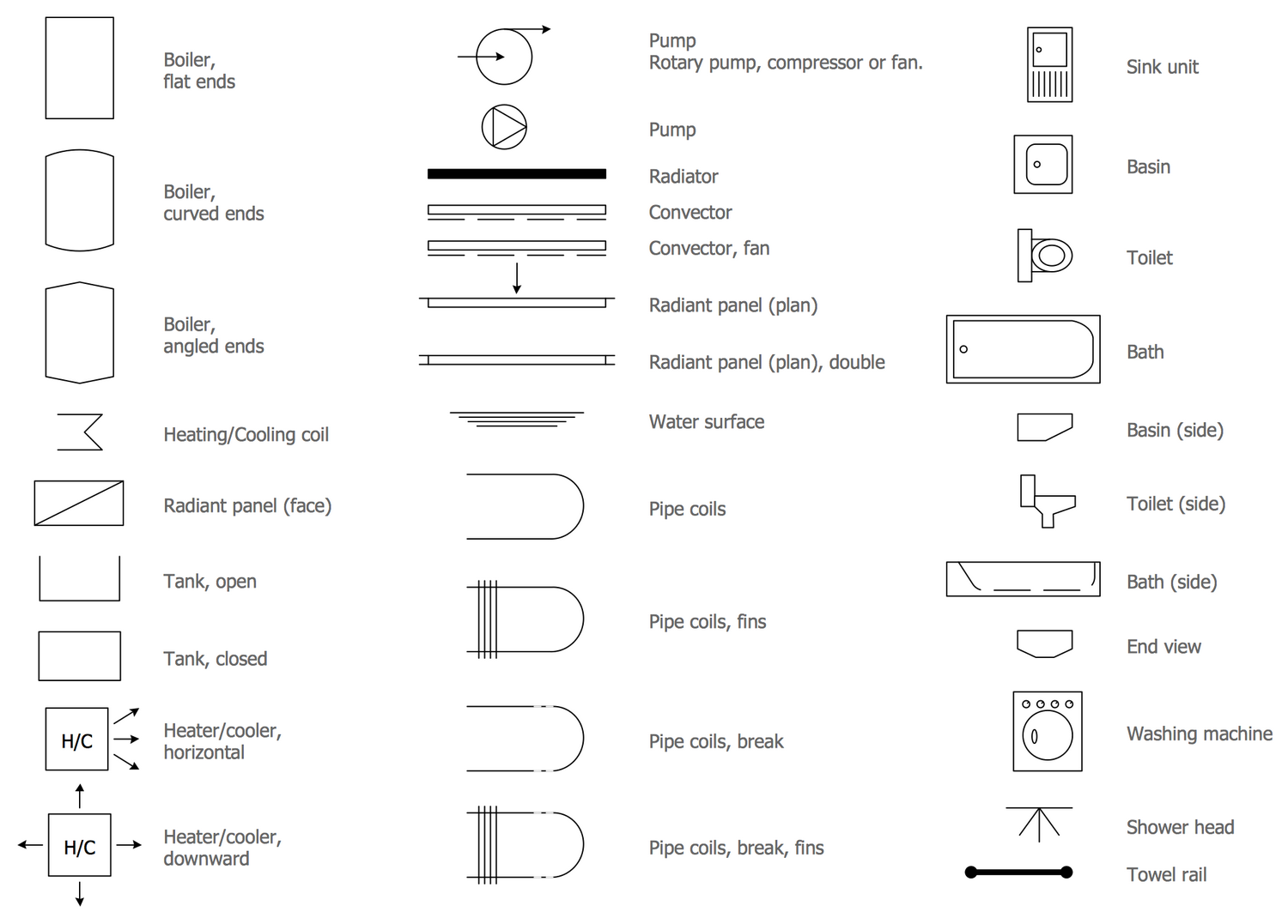
Pipe Drawing Symbols - Valves are categorized under the following headings: Web they provide a visual representation of the process flow and help in understanding the system layout. Storage tanks, reactors, columns, drums, etc. Pressure, temperature, flow, level, switches, alarms, and miscellaneous. Various symbols are used to indicate piping components, instrumentation, equipments in engineering drawings such as piping and instrumentation diagram (p&id), isometric drawings, plot plan, equipment layout, welding drawings etc. All components are represented using various p&id symbols. 1.2 this set of standard symbols is intended for use on piping system diagrammatics and arrangements for ships. 6 provides symbols for plumbing components. Piping symbol chart for piping isometric or p&id. These symbols are essential for engineers, operators, and workers to understand the layout, operation, and interconnections of the piping.
Web p&id symbols for piping. Figure 16 lists and explains four. 2.6 figure 6 provides symbols for plumbing components. Knowing the piping isometric symbols will help in recognizing the instrument and special piping items in. Pipe drawings are much different from specific weld symbols but they do have a similar relationship from part to symbol. How to read piping isometric drawing? Feature of piping drawing symbols. Some individuals will not see these in their line of work but it is important to be aware of them. Pipe and instrument diagram symbols. Web what does p&id mean?
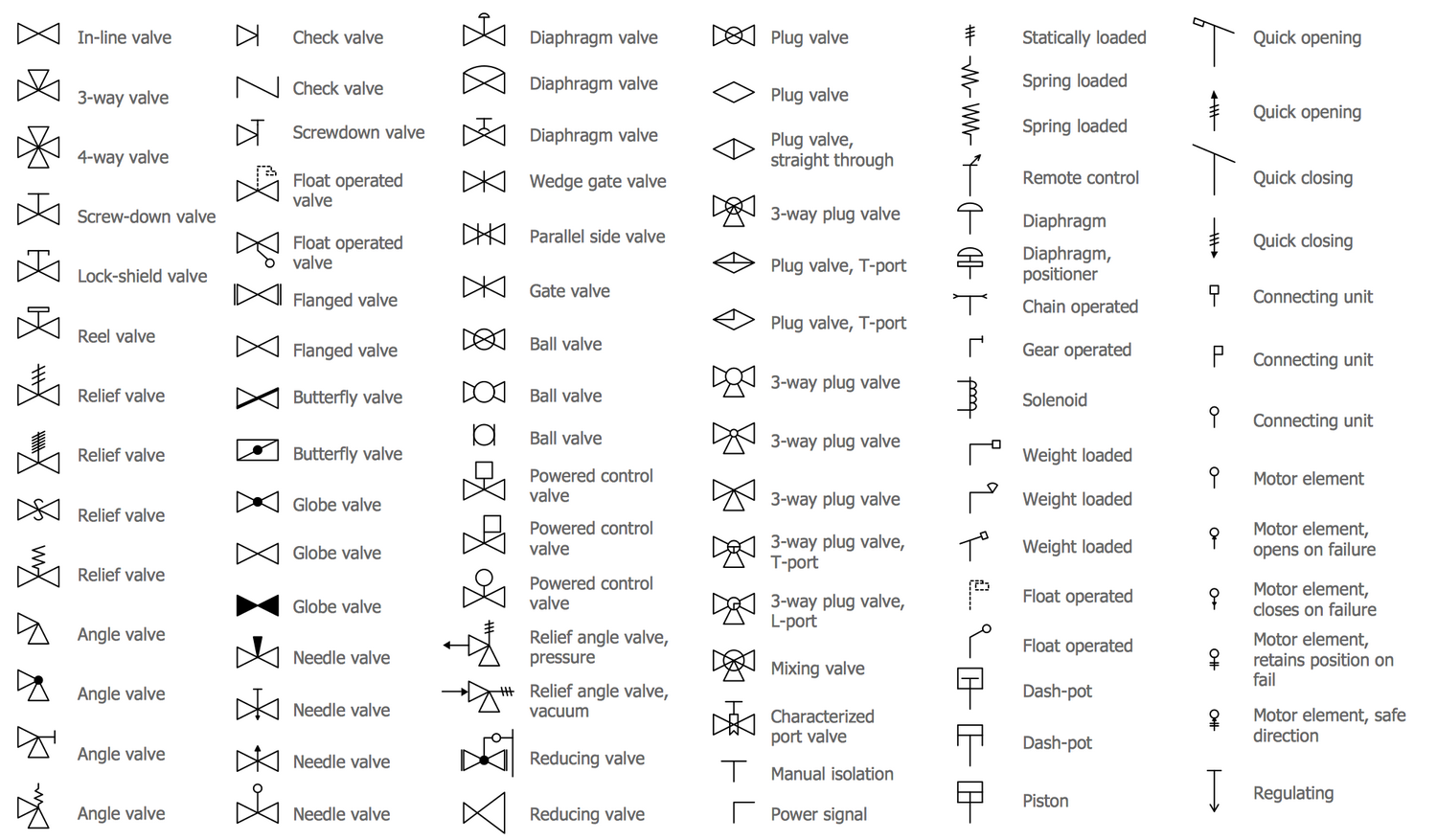
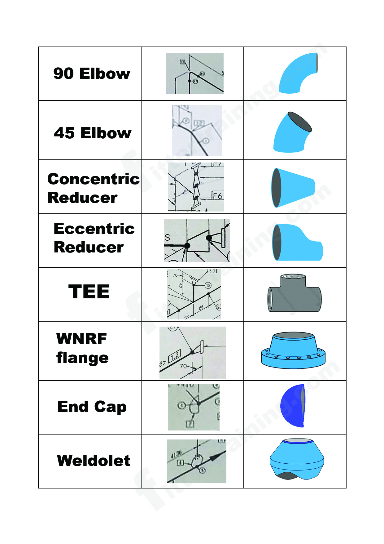
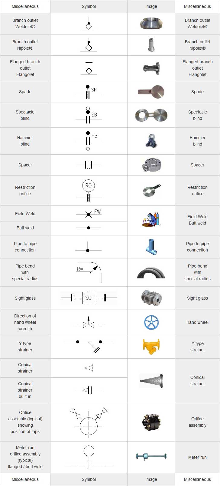
Symbols are shown in black lines. 7 provides symbols for pipe and pipe fittings. 2.2 figure 2 provides symbols for valves. Web pipe drawings are much different from specific weld symbols but they do have a similar relationship from part to symbol. 2.7 figure 7 provides symbols for pipe and pipe fittings. Web in addition to the normal symbols used on p&ids to represent specific pieces of equipment, there are miscellaneous symbols that are used to guide or provide additional information about the drawing. What is piping isometric drawing? Centrifugal pump, gear pump, diaphragm pump, etc. Figure 16 lists and explains four. Web what does p&id mean?
:max_bytes(150000):strip_icc()/plumbing-symbols-89701714-3b74c69d4bd44d488462734875967583.jpg)
How to Draw a Plumbing Plan for Your Next Remodeling Project
Gate valve, globe valve, check valve, ball valve, butterfly valve, etc. 2.7 figure 7 provides symbols for pipe and pipe fittings. By using these standardized symbols, engineers and operators can communicate effectively and ensure consistency in the design and operation of process systems. What is piping isometric drawing? Pressure, temperature, flow, level, switches, alarms, and miscellaneous.
Piping and Instrumentation Diagram Software
Web these symbols are categorized under the following headings: Knowing the piping isometric symbols will help in recognizing the instrument and special piping items in. Valves are categorized under the following headings: Some individuals will not see these in their line of work but it is important to be aware of them. As with weld symbols, pipe symbols are a.
isometric pipe drawing fittings symbol Fitter training
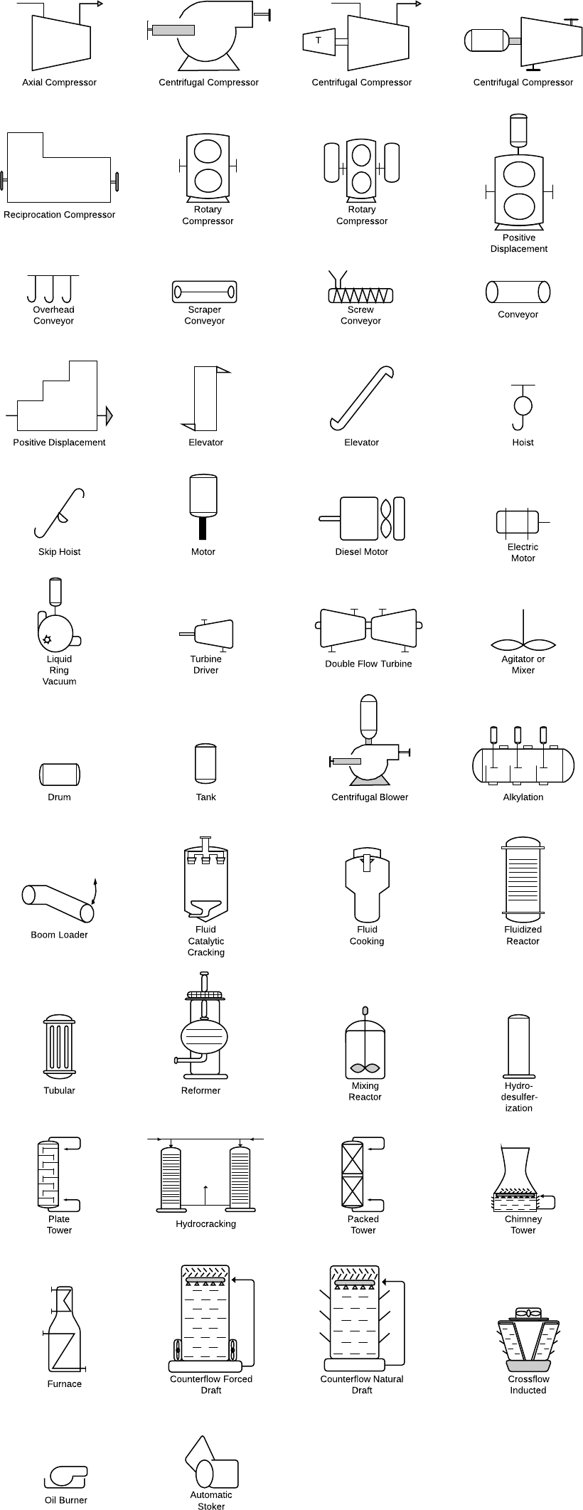
2.1 figure 1 provides symbols for strainers, separators, and filters. Web piping and instrument diagram standard symbols detailed documentation provides a standard set of shapes & symbols for documenting p&id and pfd, including standard shapes of instrument, valves, pump, heating exchanges, mixers, crushers, vessels, compressors, filters, motors and connecting shapes. 2.8 figure 8 provides symbols for noise. 5 provides symbols.

What is Piping Isometric drawing? How to Read Piping Drawing? ALL
Web these symbols are categorized under the following headings: As with weld symbols, pipe symbols are a reflection of what that part would look like in theory. Web what does p&id mean? Web we've broken them down into seven main groups: 6 provides symbols for plumbing components.

Piping Isometric Drawing Symbols Pdf at Explore
Web piping and instrument diagram standard symbols detailed documentation provides a standard set of shapes & symbols for documenting p&id and pfd, including standard shapes of instrument, valves, pump, heating exchanges, mixers, crushers, vessels, compressors, filters, motors and connecting shapes. 5 provides symbols for fans, pumps, and turbines. Pipe drawings are much different from specific weld symbols but they do.
Piping and Instrumentation Symbols Instrumentation Tools
2.8 figure 8 provides symbols for noise. Pipe drawings are much different from specific weld symbols but they do have a similar relationship from part to symbol. Piping and instrumentation diagrams are graphical representations of a process system. Web type of piping components: Checkout list of such symbols given below.
Piping Isometric Drawing Symbols Pdf at Explore
Piping and instrumentation diagrams are graphical representations of a process system. Web pipe drawings are much different from specific weld symbols but they do have a similar relationship from part to symbol. Globe, angle, check, ball, butterfly, gate, relief, manifolds, control, noise control, and. Gate valve, globe valve, check valve, ball valve, butterfly valve, etc. Symbols are shown in black.

Piping Isometric Drawings The Piping Engineering World
These are fundamental to every standardized engineering project. Pipe and instrument diagram symbols. Web p&id symbols refer to the standard notations and graphical representations used on piping and instrumentation diagrams (p&ids) to depict the components and systems involved in process flows within a facility. Web we've broken them down into seven main groups: These symbols are essential for engineers, operators,.
Pipe Symbols Interpretation of Metal Fab Drawings
Some individuals will not see these in their line of work but it is important to be aware of them. Web pipe drawings are much different from specific weld symbols but they do have a similar relationship from part to symbol. Web what does p&id mean? 2.1 figure 1 provides symbols for strainers, separators, and filters. Pipe drawings are much.
Piping Isometric Drawing Symbols Pdf at Explore
These symbols are essential for engineers, operators, and workers to understand the layout, operation, and interconnections of the piping. Web a p&id or process and instrumentation diagram provides a detailed graphical representation of the actual process system that includes the piping, equipment, valves, instrumentation, and other process components in the system. Web p&id symbols refer to the standard notations and.
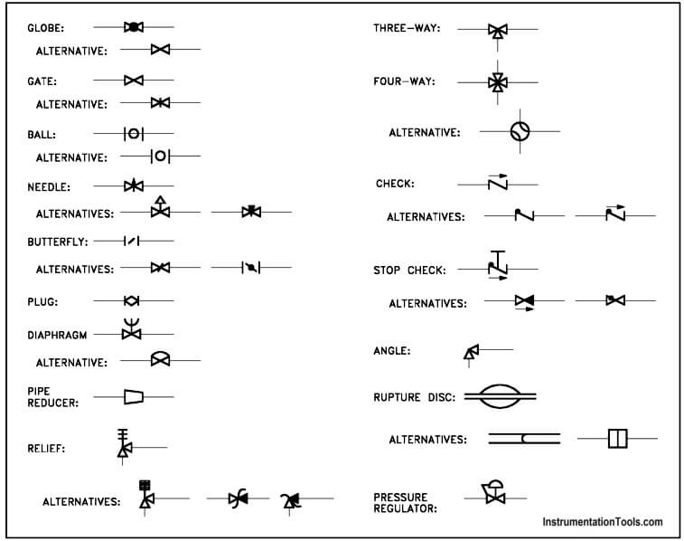
Web Piping And Instrumentation Diagrams (P&Ids) Use Specific Symbols To Show The Connectivity Of Equipment, Sensors, And Valves In A Control System.
2.2 figure 2 provides symbols for valves. Solid lines for process pipes, dashed lines for instrument signals, etc. Users can also import svg and other image files to create a custom p&id library for any situation. Gate valve, globe valve, check valve, ball valve, butterfly valve, etc.
With Lucidchart, It's Easy To Access All Of The Featured P&Id Symbols.
Symbols are shown in black lines. P&id is an abbreviation meaning ‘ piping and instrumentation diagram ‘. Web piping symbols for isometric drawings. Some individuals will not see these in their line of work but it is important to be aware of them.
Piping Symbol Chart For Piping Isometric Or P&Id.
Pressure, temperature, flow, level, switches, alarms, and miscellaneous. By using these standardized symbols, engineers and operators can communicate effectively and ensure consistency in the design and operation of process systems. Equipment, piping, vessels, heat exchangers, pumps, instruments, and valves. Checkout list of such symbols given below.
These Are Fundamental To Every Standardized Engineering Project.
All components are represented using various p&id symbols. Web these symbols are categorized under the following headings: Various symbols are used to indicate piping components, instrumentation, equipments in engineering drawings such as piping and instrumentation diagram (p&id), isometric drawings, plot plan, equipment layout, welding drawings etc. Lighter lines show connected pipe, and are not parts of the symbols.