Pipework Drawings
Pipework Drawings - It is the most important deliverable of piping engineering department. The drawing sheet sizes shall be any of the following. Commonly these are drawn at a 30 degree angle from the horizontal plane. These symbols are used to indicate the type of connection, the direction of flow, and the size of the pipe. Process flow diagram (pfd) piping and instrumentation drawing (p&id) plot. Web piping isometric drawing is an isometric representation of single pipe line in a plant. Piping joint types, weld types. Web a piping isometric drawing provides all the required information like: Web open api the smartdraw api allows you to skip the drawing process and generate diagrams from data automatically. Many abbreviations are common and are regularly used in the drawings but few of the abbreviation are new and unique for a particular drawing.
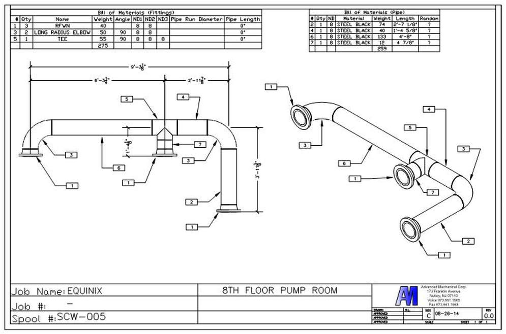
These drawings include details such as pipe sizes, lengths, angles, and bends, as well as the location of valves, fittings, and supports. By continuing to use the website, you consent to the use of cookies. A piping single line drawing (or piping one line drawing) is a piping drawing that shows the size and location of pipes, fittings and valves. Web a piping isometric drawing is a technical drawing that depicts a pipe spool or a complete pipeline using an isometric representation. Piping and component descriptions with size, quantity, and material codes. Explore smartdraw check out useful features that will make your life easier. Shape data add data to shapes, import data, export manifests, and create data rules to change dashboards that update. It is drawn to scale so the relationships of the. Web piping isometrics also provide vital information about the dimensions and the technical specifications of the pipes. How to read iso drawings.
It is the most important deliverable of piping engineering department. Web how to read piping isometric drawing symbols. They serve as precise illustrations providing essential information about the layout, dimensions, materials, and key components of a pipeline system. Web tools you’ll need to create pipe drawings: Web this is a certified workshop! It is drawn to scale so the relationships of the. Web a piping isometric drawing is a technical drawing that depicts a pipe spool or a complete pipeline using an isometric representation. Web piping symbols, also known as pipe drawings, are a set of symbols used in metal fabrication drawings to represent the various types of pipes and fittings used in industrial piping systems. Web piping isometrics also provide vital information about the dimensions and the technical specifications of the pipes. Web pipeline drawings include pipeping and instrumentation diagrams ( p&id ), isometric drawings, and many more.
Pipes Drawing at GetDrawings Free download
The drawing axes of the isometrics intersect at an angle of 60°. Process flow diagram (pfd) piping and instrumentation drawing (p&id) plot. Piping joint types, weld types. Web piping isometric drawing is an isometric representation of single pipe line in a plant. How to read iso drawings.
PIPING DRAWINGS
Web in this article, we will explore all those piping drawings that are required to execute piping work. In very complex or large piping systems, piping isometrics are essential to the design and manufacturing phases of a project. Explore smartdraw check out useful features that will make your life easier. The instructor explains the state of art in. Web tools.
Pipe Drawing at GetDrawings Free download
It is the most important deliverable of piping engineering department. When drawing piping diagrams, having the right tools is essential. Whenever you start reading a piping drawing or document, you can see many abbreviations on these drawings/documents. By continuing to use the website, you consent to the use of cookies. Web pipeline drawings include pipeping and instrumentation diagrams ( p&id.

How to Draw Isometric Pipe Drawings in Autocad Gautier Camonect
How to read iso drawings. In very complex or large piping systems, piping isometrics are essential to the design and manufacturing phases of a project. It is drawn to scale so the relationships of the. We are concluding our first pipefitter series run with a video on how to draw isometric drawings. Piping fabrication work is based on isometric drawings.

How to read piping isometric drawing, Pipe fitter training, Watch the
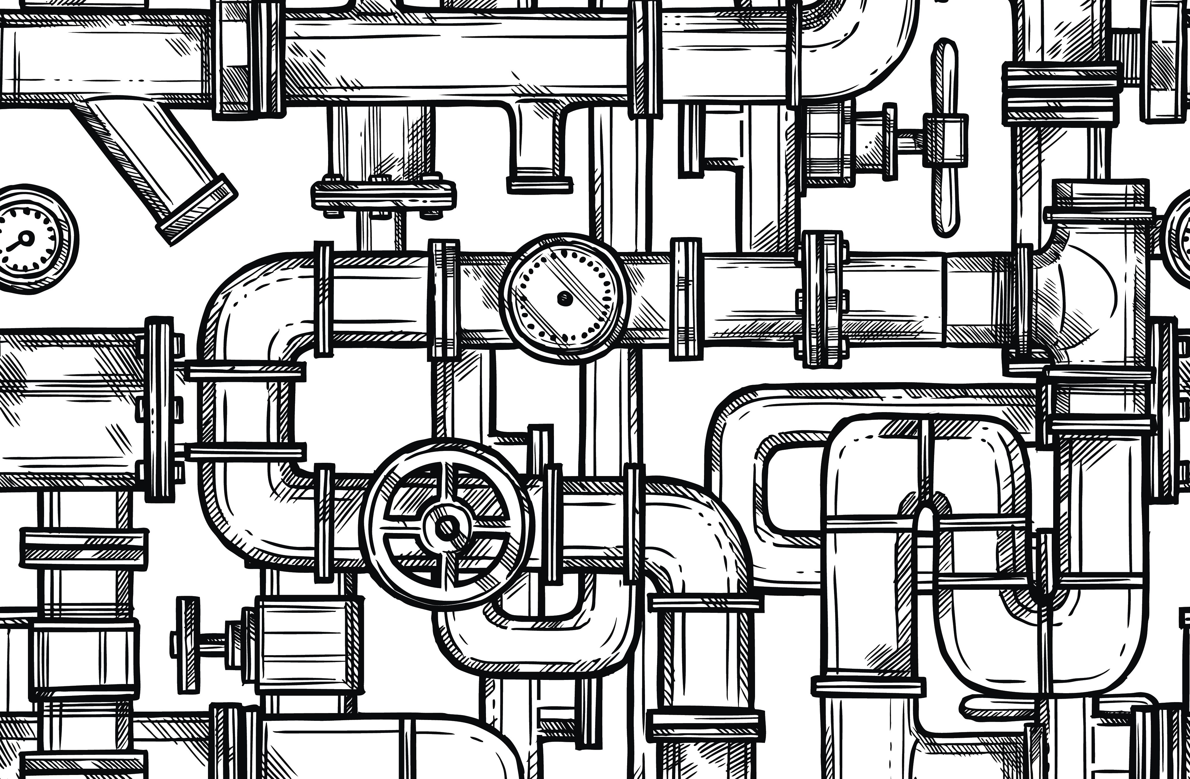
Web piping symbols, also known as pipe drawings, are a set of symbols used in metal fabrication drawings to represent the various types of pipes and fittings used in industrial piping systems. Web a piping isometric drawing provides all the required information like: Web this is a certified workshop! It is the most important deliverable of piping engineering department. Web.
Isometric Piping Drawings Advenser
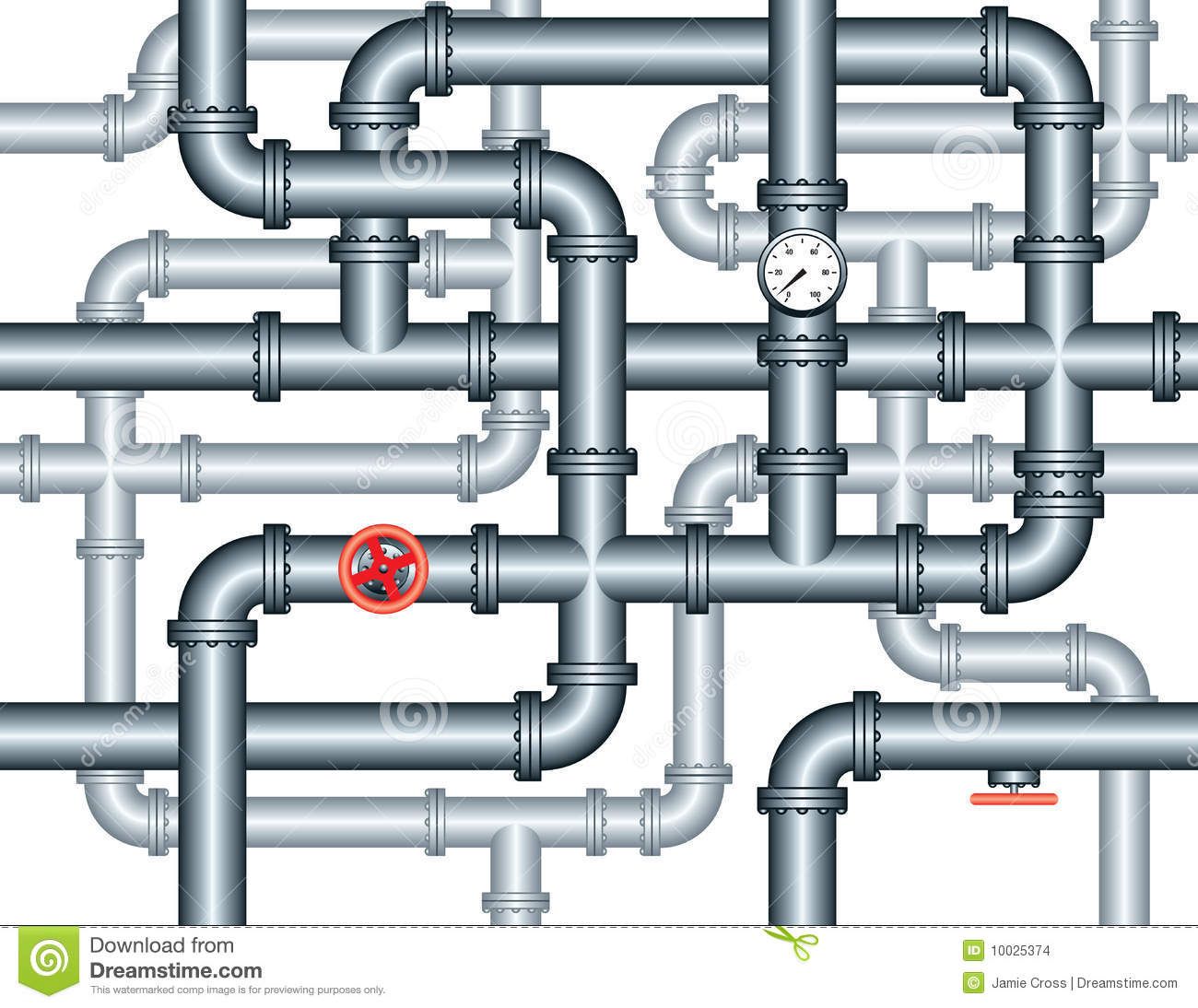
The drawing axes of the isometrics intersect at an angle of 60°. A piping single line drawing (or piping one line drawing) is a piping drawing that shows the size and location of pipes, fittings and valves. These drawings include details such as pipe sizes, lengths, angles, and bends, as well as the location of valves, fittings, and supports. Web.
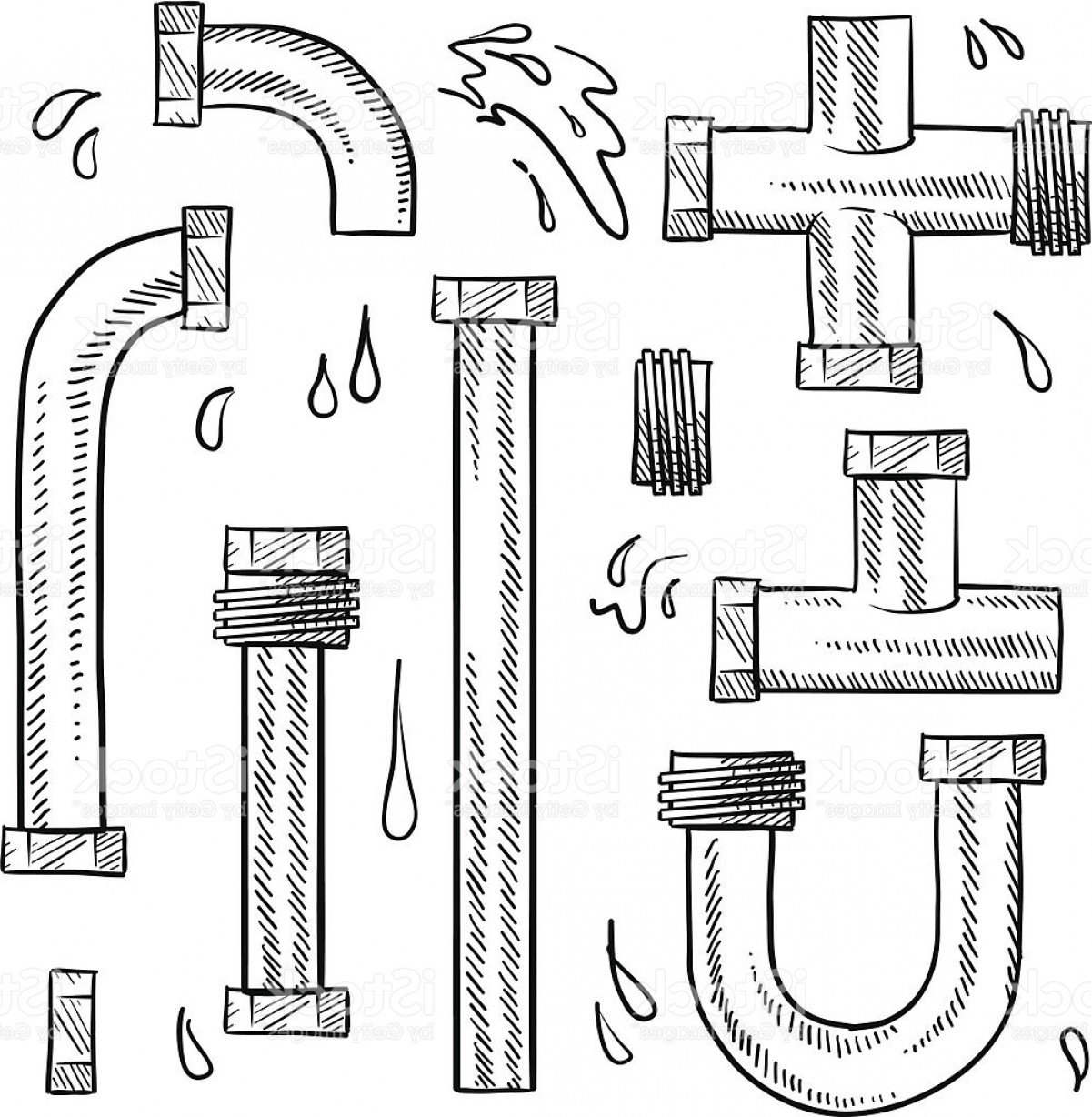
Pipe Sketch at Explore collection of Pipe Sketch
The drawing sheet sizes shall be any of the following. Web pipe drawings are presented in an isometric view (iso.) this view is drawn in order to show a pictorial view of what is needed. Web piping isometric drawing is an isometric representation of single pipe line in a plant. Web tools you’ll need to create pipe drawings: General arrangement.
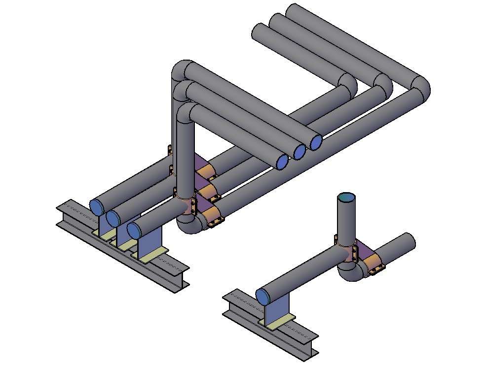
3D Pipe Drawing In AutoCAD File Cadbull
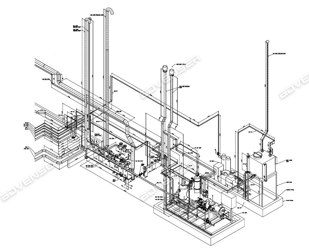
Browse piping diagram templates and examples you can make with smartdraw. Web a piping isometric drawing is a technical drawing that depicts a pipe spool or a complete pipeline using an isometric representation. Web piping isometrics are generally produced from orthographic drawings and are important pieces of information to engineers. Web tools you’ll need to create pipe drawings: When drawing.

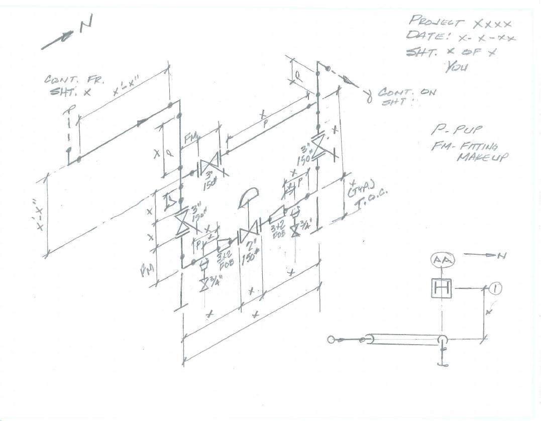
How to read piping isometric drawing pdf fleetlio
Web open api the smartdraw api allows you to skip the drawing process and generate diagrams from data automatically. General arrangement drawing (gad)/piping plan drawing. Web pipe drawings are presented in an isometric view (iso.) this view is drawn in order to show a pictorial view of what is needed. Web a piping system drawing may be represented by the.
How to read iso pipe drawings perlogistics
A piping single line drawing (or piping one line drawing) is a piping drawing that shows the size and location of pipes, fittings and valves. Shape data add data to shapes, import data, export manifests, and create data rules to change dashboards that update. The drawing sheet sizes shall be any of the following. It is the most important deliverable.
Web How To Read Piping Isometric Drawing Symbols.
Here are the key tools you’ll need to start your project: Commonly these are drawn at a 30 degree angle from the horizontal plane. Shape data add data to shapes, import data, export manifests, and create data rules to change dashboards that update. Web tools you’ll need to create pipe drawings:
P&Id Type Of Drawings Provide A Comprehensive Overview Of A Pipeline System, While Pfds Illustrate The Entire Process.
We are concluding our first pipefitter series run with a video on how to draw isometric drawings. Web pipe drawings are presented in an isometric view (iso.) this view is drawn in order to show a pictorial view of what is needed. The piping isometrics software can be extended to process data from other 3d cad and plant design systems. Web a piping system drawing may be represented by the following three methods.
It Is Drawn To Scale So The Relationships Of The.
Web open api the smartdraw api allows you to skip the drawing process and generate diagrams from data automatically. Web knowing that the piping arrangement drawing is a plan, or top, view drawing, a pipe can be determined to be turning north, south, east, or west when oriented relative to the drawing’s north arrow. A piping single line drawing (or piping one line drawing) is a piping drawing that shows the size and location of pipes, fittings and valves. These drawings are impelled to supply a more detailed and authentic representation, emphasising the pipes, valves and other components’ shape, size and.
Cad Software With Piping Tools Preinstalled.
Browse piping diagram templates and examples you can make with smartdraw. Process flow diagram (pfd) piping and instrumentation drawing (p&id) plot. Web a piping isometric drawing provides all the required information like: When drawing piping diagrams, having the right tools is essential.