Section Line In Engineering Drawing
Section Line In Engineering Drawing - The line that indicates the plane where the cut is made is called the section line. Their basic purpose is to show circular/cylindrical features in a drawing, which. The line is drawn using a thin line with alternating long and short dashes. See the difference between cutting plane, cutting plane line, section lining, full sections,. To illustrate where solid material be exposed by such a cut, section lining is. These views are usually represented via annotated section lines and labels. Centerlines are one of the most frequently used tools in engineering drawing. Web section lines are used to show the cut surfaces of an object in section views. Web this section will cover the different types of section views, corresponding technical vocabulary, and help you determine which section view would best communicate. Web section cut indicators identifies the plane where, how and on which planes the section cut is made.
In a standard set of architectural plans on a small. Find out how to make engineering. Cutting plane lines are long lines, thickened ar ends and thin elsewhere, with alternately long and short dashes of proportion ranging from 4:1 to 6:1. These views are usually represented via annotated section lines and labels. The line is drawn using a thin line with alternating long and short dashes. For most purposes, the general use symbol. One of the best ways to communicate one's ideas is through some form of picture or drawing. Web section cut indicators identifies the plane where, how and on which planes the section cut is made. The line that indicates the plane where the cut is made is called the section line. This is especially true for the engineer.
The main elements of the section view are: This is especially true for the engineer. Web center lines in an engineering drawing show the center of a round or cylindrical shape. Web learn how to sketch and read sectional views of objects in engineering drawings. Section lines, or hatching, that represent the cut surface usually consist of thin parallel lines, as shown below, drawn at an angle of approximately 45° to the principal edges or axes of the part. In the figure a regular multiview drawing and a. For most purposes, the general use symbol. Web section cut indicators identifies the plane where, how and on which planes the section cut is made. They are fine, dark lines. Web section lines and symbols.

Sectional View in Engineering Drawing YouTube
One of the best ways to communicate one's ideas is through some form of picture or drawing. Web section drawing in engineering. Web section lines and symbols. The line that indicates the plane where the cut is made is called the section line. This is especially true for the engineer.
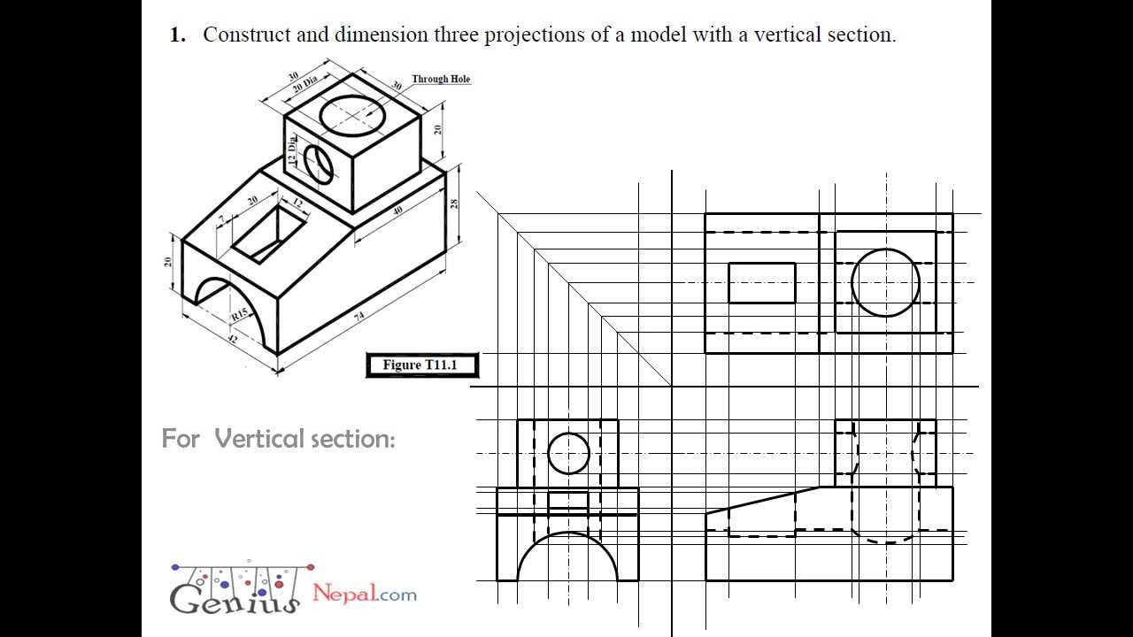
Engineering Drawing Tutorials/Orthographic and sectional views ( T 11.1
Web center lines in an engineering drawing show the center of a round or cylindrical shape. To illustrate where solid material be exposed by such a cut, section lining is. One of the best ways to communicate one's ideas is through some form of picture or drawing. This is especially true for the engineer. In a standard set of architectural.

Full Sectioning Problem 1 Engineering Drawing 9.1 YouTube
Section line, section reference arrow, section. The main elements of the section view are: Used to indicate where the cutting plane cuts the material. One of the best ways to communicate one's ideas is through some form of picture or drawing. Web section drawing in engineering.
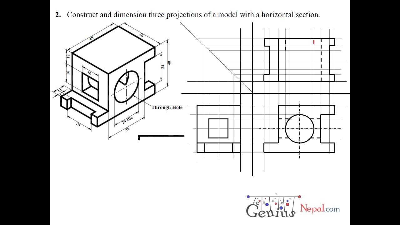
Engineering Drawing Tutorials/Orthographic and sectional views ( T 11.3
Find out how to make engineering. Cutting plane lines are long lines, thickened ar ends and thin elsewhere, with alternately long and short dashes of proportion ranging from 4:1 to 6:1. Used to indicate where the cutting plane cuts the material. Web sectional drawings are multiview technical drawings that contain special views of a part or parts, a view that.
Section Lines ToolNotes
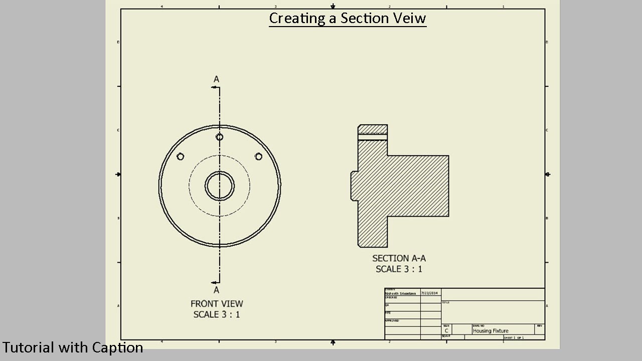
Web the picture below shows how our object would be represented in the engineering drawing. Web section cut indicators identifies the plane where, how and on which planes the section cut is made. The line is drawn using a thin line with alternating long and short dashes. This is especially true for the engineer. Web section lines on a drawing.
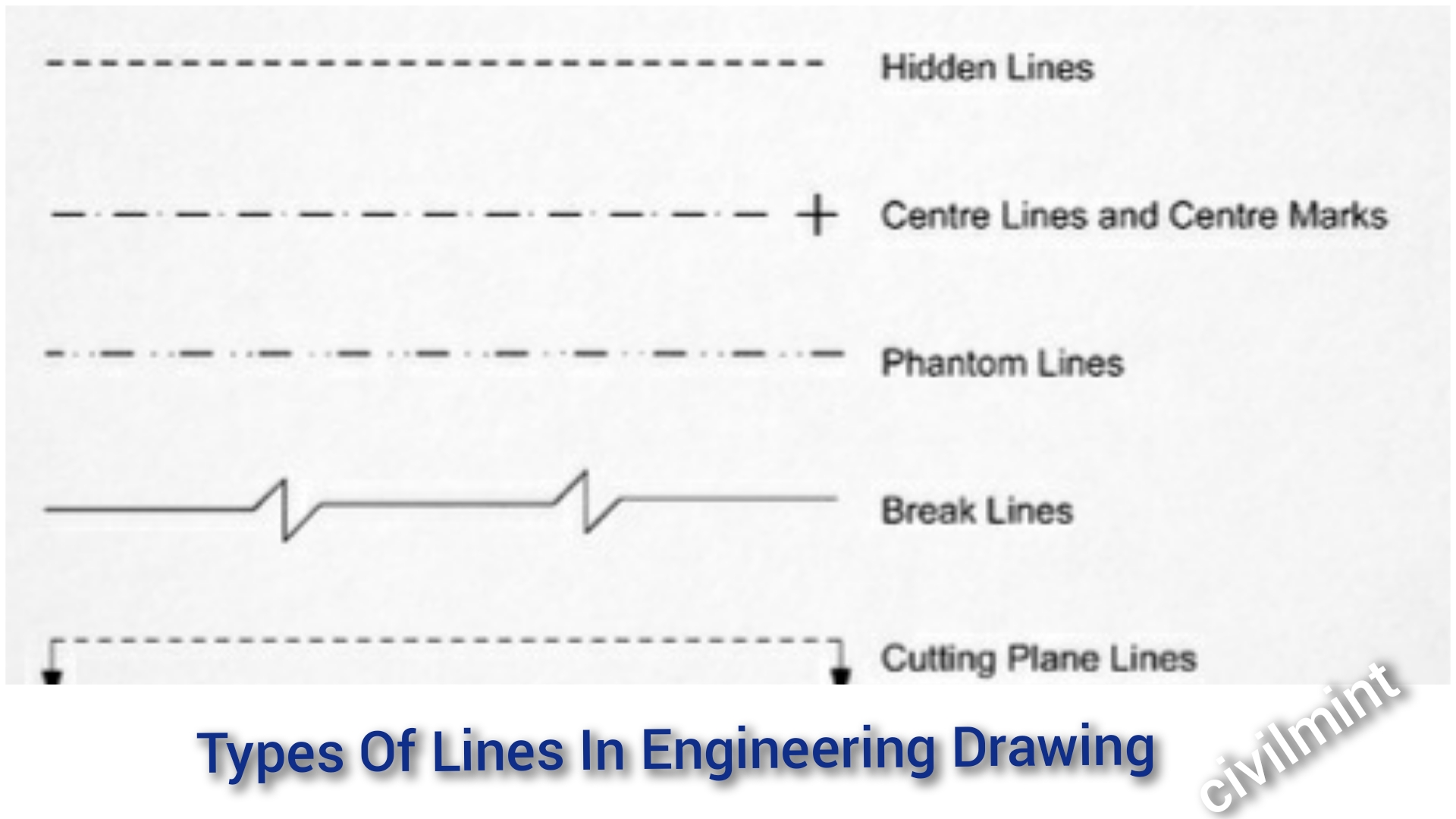
Types Of Lines In Engineering Drawing
In a standard set of architectural plans on a small. Web learn how to sketch and read sectional views of objects in engineering drawings. Their basic purpose is to show circular/cylindrical features in a drawing, which. In a section view, the object is shown as if it were cut along the cutting plane line. Web a section, take a slice.

Sectional View in Engineering Drawing YouTube
The line is drawn using a thin line with alternating long and short dashes. Their basic purpose is to show circular/cylindrical features in a drawing, which. Web section cut indicators identifies the plane where, how and on which planes the section cut is made. Find out how to make engineering. Used to indicate where the cutting plane cuts the material.

Sectional Views
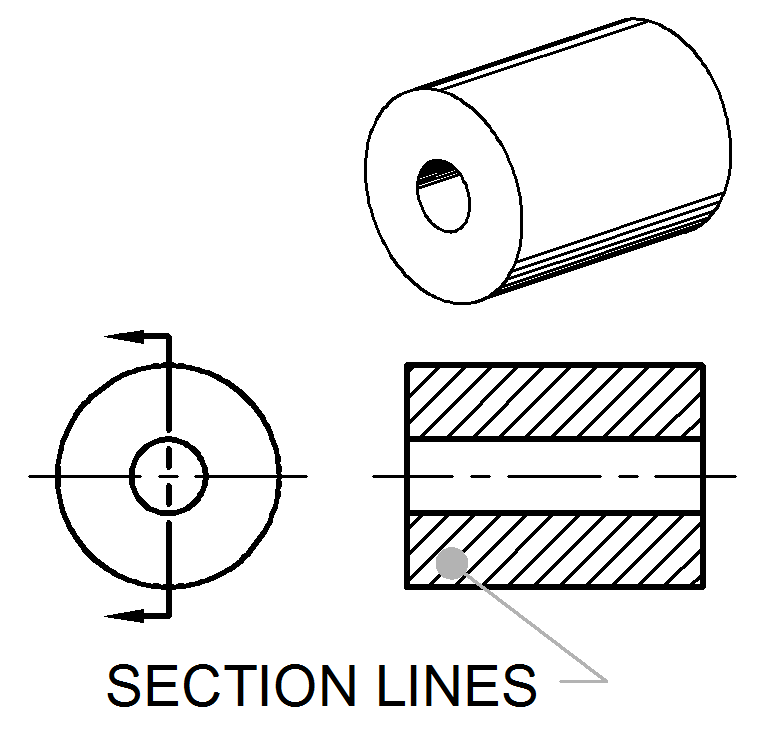
Web section lines on a drawing indicate a surface that has been cut or sliced in a section view. Section line, section reference arrow, section. Web section lining is a method of representing internal features of an object in an engineering drawing. Centerlines are one of the most frequently used tools in engineering drawing. In a section view, the object.

SECTION DRAWINGS BRANDON OWENS' PORTFOLIO
Web this section will cover the different types of section views, corresponding technical vocabulary, and help you determine which section view would best communicate. Section lines, or hatching, that represent the cut surface usually consist of thin parallel lines, as shown below, drawn at an angle of approximately 45° to the principal edges or axes of the part. Centerlines are.
Sectional View Engineering Drawing Exercises at GetDrawings Free download
Used to indicate where the cutting plane cuts the material. In a standard set of architectural plans on a small. The line that indicates the plane where the cut is made is called the section line. Web learn the different types of lines and views in engineering drawing, such as section line, centre line, extension line, break line and more..
Web Section Lines On A Drawing Indicate A Surface That Has Been Cut Or Sliced In A Section View.
In a section view, the object is shown as if it were cut along the cutting plane line. Section lines are thin and the symbols (type of lines) are chosen according to the material of the object. This is especially true for the engineer. Web section lines are used to show the cut surfaces of an object in section views.
Web The Picture Below Shows How Our Object Would Be Represented In The Engineering Drawing.
To illustrate where solid material be exposed by such a cut, section lining is. Web center lines in an engineering drawing show the center of a round or cylindrical shape. Various types of section lines may indicate the type of material cut by. Centerlines are one of the most frequently used tools in engineering drawing.
Web In Short, A Section Drawing Is A View That Depicts A Vertical Plane Cut Through A Portion Of The Project.
They are fine, dark lines. Web a section, take a slice through the building or room and show the relationship between floors, ceilings, walls and so on. One of the best ways to communicate one's ideas is through some form of picture or drawing. In a standard set of architectural plans on a small.
Web This Section Will Cover The Different Types Of Section Views, Corresponding Technical Vocabulary, And Help You Determine Which Section View Would Best Communicate.
Web the diagonal lines on the section drawing are used to indicate the area that has been theoretically cut. Their basic purpose is to show circular/cylindrical features in a drawing, which. Web learn the different types of lines and views in engineering drawing, such as section line, centre line, extension line, break line and more. The line that indicates the plane where the cut is made is called the section line.