Single Line Drawing Electrical
Single Line Drawing Electrical - It's a vital tool for conveying the structure and components of the system in a clear and concise manner. Web a circuit diagram allows you to visualize how components of a circuit are laid out. Since then, no team had ever had more than four in an inning. Usually they are given in form of electrical circuits between two lines which are representing control voltage potentials. Open an wiring diagram or circuit drawing template—not just a blank screen. A diagram which shows, by means of single lines and graphic symbols, the course of an electric circuit or system of circuits and the component devices or parts used therein. We will looking a normal set of plans o. In this post you’ll learn what is single line diagram and why do we need it. Web an electrical single line diagram is a graphical representation of an electrical system’s components and connections. It is a simplified drawing of the whole system or a portion of the power system that shows the electrical placement of all major equipment.
Our electrical power systems primarily contain three phases of ac circuits. Windows terminal is back with another preview release! It is a simplified drawing of the whole system or a portion of the power system that shows the electrical placement of all major equipment. It is the first step in preparing a critical response plan, allowing you to become thoroughly familiar with the electrical distribution system layout and design in your facility. Transmission, distribution, and power transformers are also three phases. Unlike single line diagrams, every drawn line matches one single wire which actually exists inside control part of the. Web published may 6, 2024 updated may 7, 2024. Smartdraw comes with thousands of detailed electrical symbols you can drag and drop to your drawings and schematics. We will looking a normal set of plans o. The recalled ovens were sold in stainless steel and black stainless with a digital control at the top of the unit.
Our electrical power systems primarily contain three phases of ac circuits. Web single line diagram (sld) we usually depict the electrical distribution system by a graphic representation called a single line diagram (sld). As the name suggests, a single line is used to denote the multiple power lines. Lines connect fuses, switches, capacitors, inductors, and more. The diagram is commonly used in designing, operating, and maintaining electrical power systems. In this course we will basics to advanced understanding of. We will looking a normal set of plans o. Web a circuit diagram allows you to visualize how components of a circuit are laid out. There’s also a lot more stuff so check out the rest of this blog. Windows terminal is back with another preview release!
how to prepare electrical single line diagram Wiring Diagram and
It is the first step in preparing a critical response plan, allowing you to become thoroughly familiar with the electrical distribution system layout and design in your facility. It is a simplified drawing of the whole system or a portion of the power system that shows the electrical placement of all major equipment. Unlike single line diagrams, every drawn line.
Electrical SingleLine Diagram Intelligent One Line Diagram ETAP
As the newest member of plano's clean fleet, this vehicle will be able to collect from 1,100 homes on a single charge. It's a vital tool for conveying the structure and components of the system in a clear and concise manner. Open an wiring diagram or circuit drawing template—not just a blank screen. In this course we will basics to.
Electrical SingleLine Diagram Electrical OneLine Diagram ETAP
Web an electrical single line diagram is a graphical representation of an electrical system’s components and connections. As the newest member of plano's clean fleet, this vehicle will be able to collect from 1,100 homes on a single charge. It is used by electricians, engineers, and technicians to understand the electrical components and connections within a system. The diagram is.
Electrical Single Line Diagram Part Two Electrical Knowhow
In this concise and informative video, i break down the learn. Web in this video, i'll explain how to read substation single line diagram (sld) in 5 simple steps. A diagram which shows, by means of single lines and graphic symbols, the course of an electric circuit or system of circuits and the component devices or parts used therein. Web.
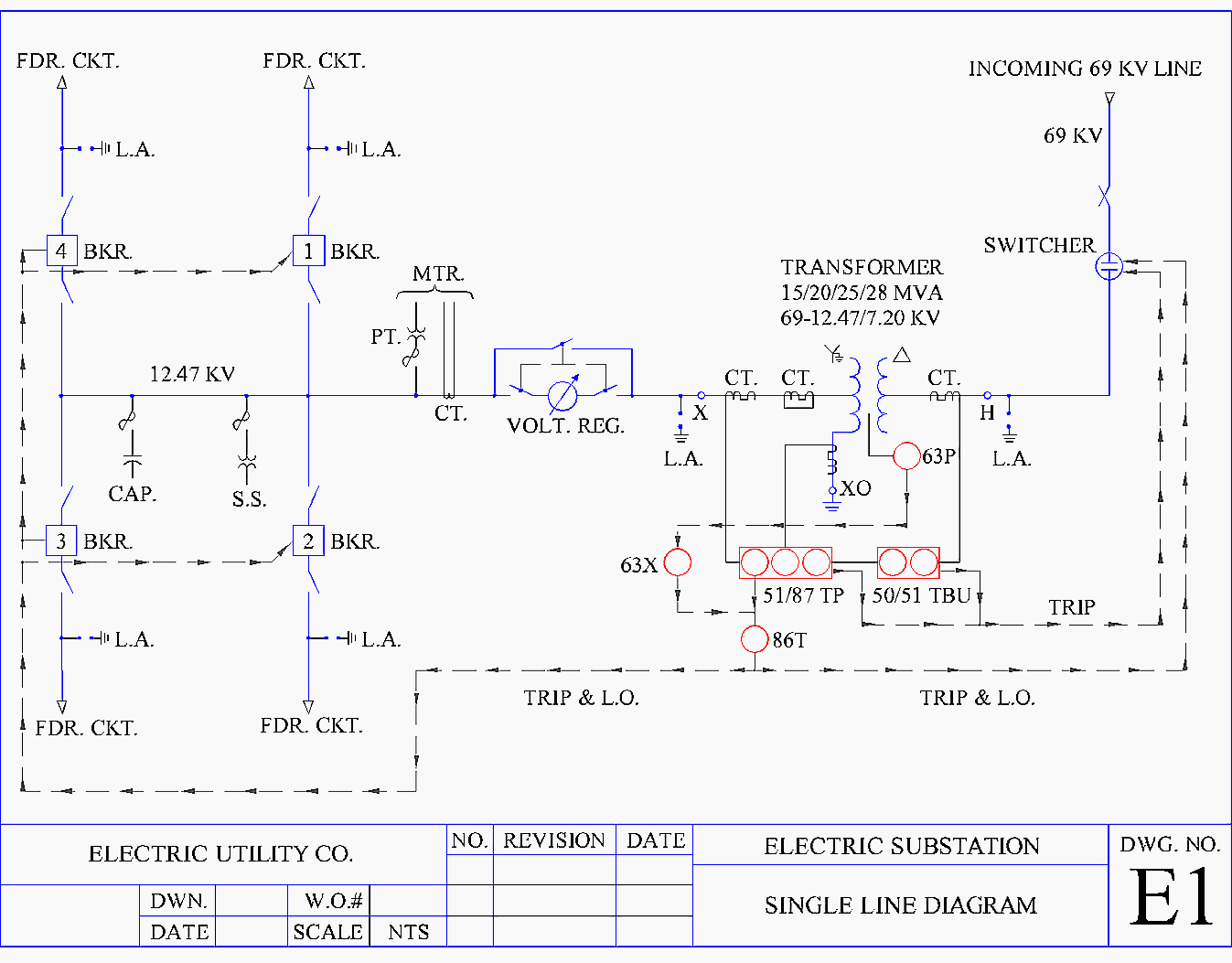
Understanding Substation Single Line Diagrams and IEC 61850 Process Bus
The diagram is commonly used in designing, operating, and maintaining electrical power systems. There’s also a lot more stuff so check out the rest of this blog. Lines connect fuses, switches, capacitors, inductors, and more. The recalled product is approximately 30 inches wide by. [1] [2] a single line in the diagram typically corresponds to more than one physical conductor:
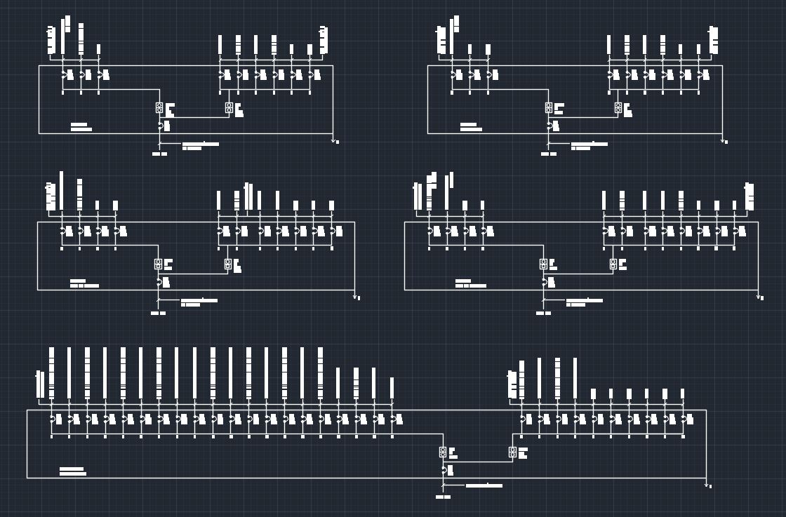
Electrical Single Line Diagram Template (DWG) — LINE DRAW CAD LAB
In this post you’ll learn what is single line diagram and why do we need it. It is used by electricians, engineers, and technicians to understand the electrical components and connections within a system. Web the single line diagram (sld) or single line scheme is a foundational diagram used in electrical engineering to represent a simplified view of an electrical.
How to Read and Understand an Electrical Single Line Diagram?
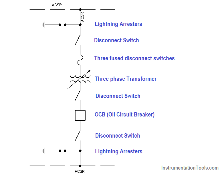
As the name suggests, a single line is used to denote the multiple power lines. Usually they are given in form of electrical circuits between two lines which are representing control voltage potentials. Since then, no team had ever had more than four in an inning. It uses standardized symbols to depict various elements such as generators, transformers, switches, motors,.
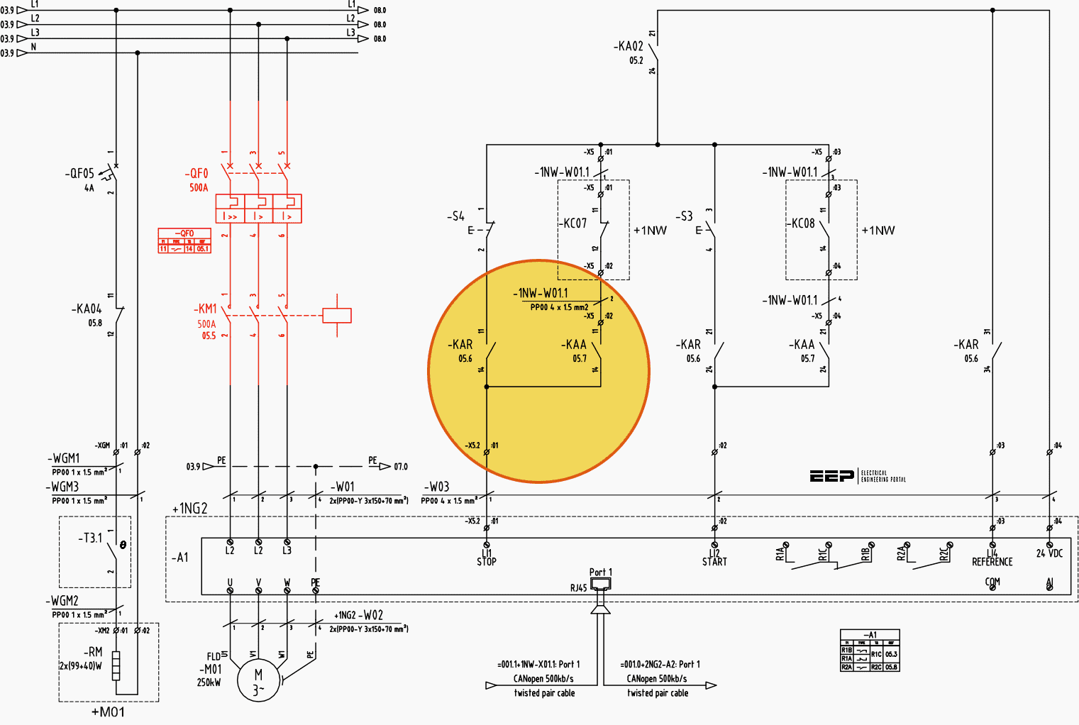
Learn to read and understand single line diagrams & wiring diagrams EEP
It is the first step in preparing a critical response plan, allowing you to become thoroughly familiar with the electrical distribution system layout and design in your facility. There’s also a lot more stuff so check out the rest of this blog. Web may 8th, 2024 2 3. Visit plano.gov/cleanfleet for more info on the environmentally friendly cars within the.
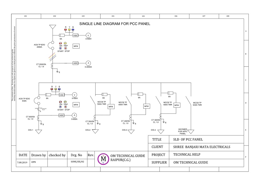
omtechguide ELECTRICAL SINGLE LINE DIAGRAM Electrical Panel
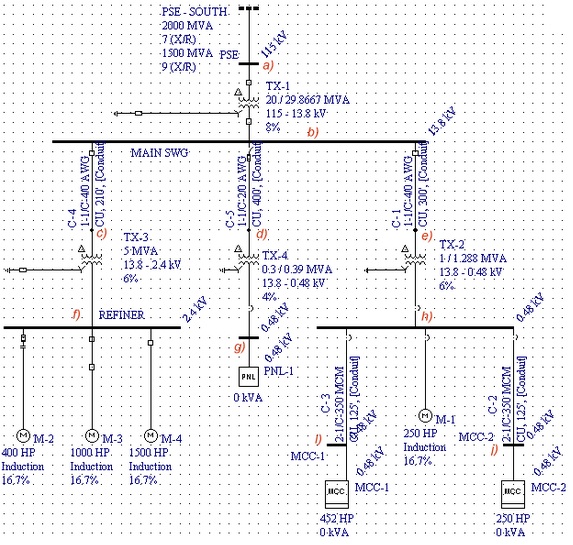
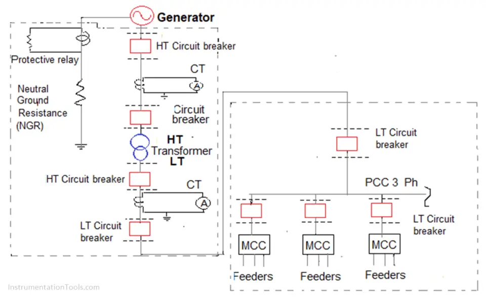
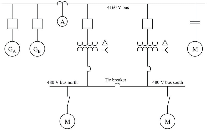
These symbols provide a simple and concise way to communicate the design and operation of an. The diagram is typically drawn using standardized symbols for each component, making it easy to understand and analyze the system. No calculation is necessary for correcting the value of the generator reactance because it is given as 0.15 p.u. Web in this video, i'll.
Singleline Electrical Diagrams Electric Power Measurement and
Web published may 6, 2024 updated may 7, 2024. It is used by electricians, engineers, and technicians to understand the electrical components and connections within a system. Symbols and lines are used to represent the nodes and connections in the system, and electrical characteristics may be included as well. It provides a visual representation of the electrical components and their.
It's A Vital Tool For Conveying The Structure And Components Of The System In A Clear And Concise Manner.
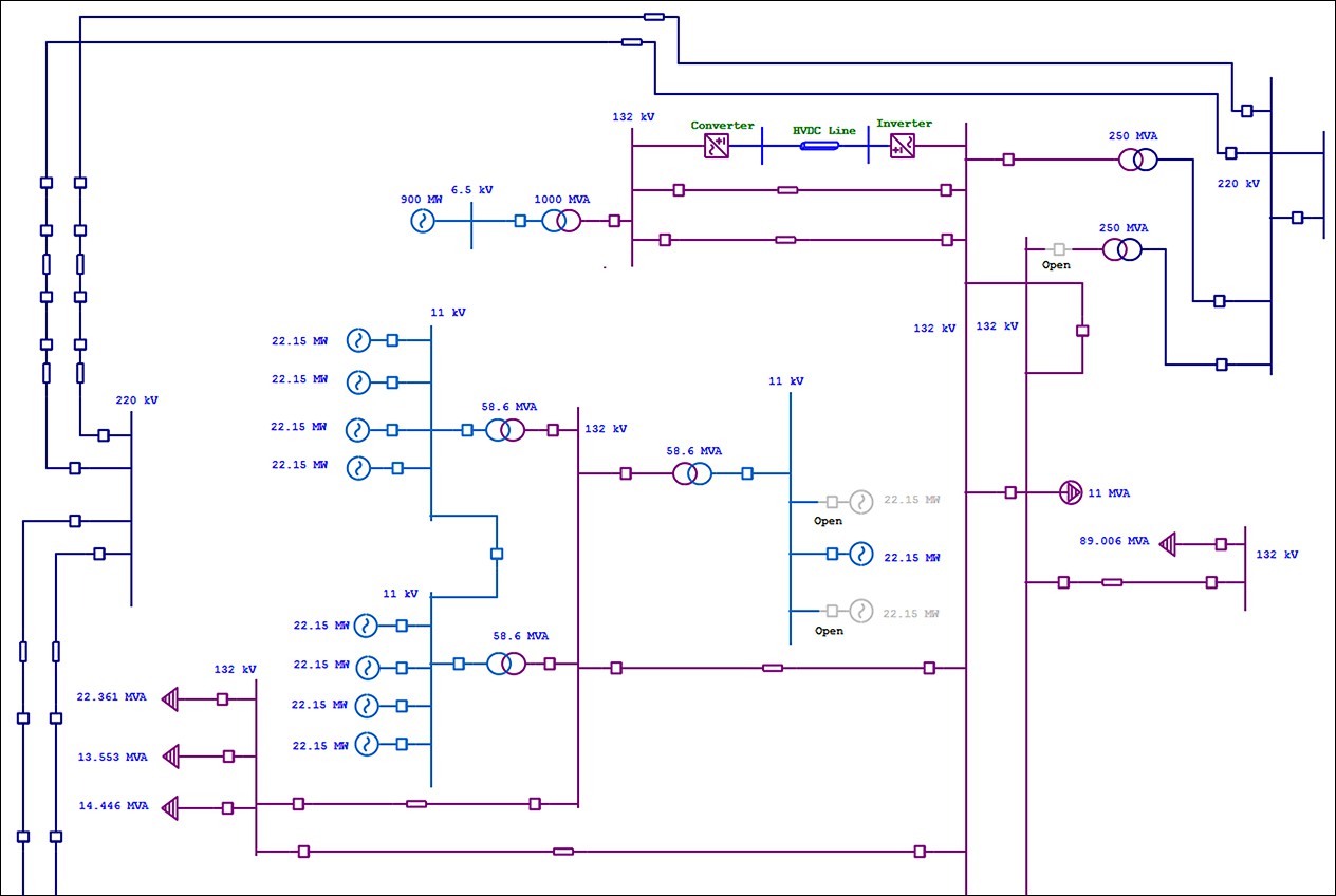
Our electrical power systems primarily contain three phases of ac circuits. Web the single line diagram (sld) or single line scheme is a foundational diagram used in electrical engineering to represent a simplified view of an electrical system or network. This diagram shows the flow of electrical power from the source to various devices, such. The recalled product is approximately 30 inches wide by.
Web Wiring Diagrams Are Used To Show Control And Signalization Principle Of Operation Inside Switchboard.
It provides a visual representation of the electrical components and their interconnections in a power system. Open an wiring diagram or circuit drawing template—not just a blank screen. As the name suggests, a single line is used to denote the multiple power lines. Since then, no team had ever had more than four in an inning.
Transmission, Distribution, And Power Transformers Are Also Three Phases.
It is used by electricians, engineers, and technicians to understand the electrical components and connections within a system. Lines connect fuses, switches, capacitors, inductors, and more. We will looking a normal set of plans o. Windows terminal is back with another preview release!
Web By The End Of This Video Will Completely Understand The Ideals Of The One Line Diagram From A Electrical Perspective.
[1] [2] a single line in the diagram typically corresponds to more than one physical conductor: The recalled ovens were sold in stainless steel and black stainless with a digital control at the top of the unit. Electrical power grids primarily consist of. Usually they are given in form of electrical circuits between two lines which are representing control voltage potentials.