Tech Drawing Symbols
Tech Drawing Symbols - Web engineering drawing abbreviations and symbols. The company or agency that prepared the drawing. Web geometric dimensioning and tolerancing, or gd&t for short, is a language of symbols used to communicate information on technical drawings. We offer you our tips which we believe are useful for dispelling uncertainty by comparing the symbol with its graphic representation. The true position theory and the specification of tolerance zones are also explained. Web the indication of surface roughness values in the surface finish symbols are shown the figure a. Web guide on using mechanical drawing symbols. The figures in the table at the left of the box are in millimetres. Note the comparison with the iso standards. Web 2025 genesis gv80 pricing.
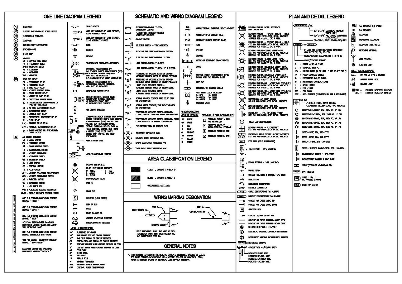
Already, we have seen that chat is reinventing how people search with more than 100 million chats to date. Web the leading designer of accelerator chips for the explosive artificial intelligence (ai) market has seen a 215% stock price run in 52 weeks, including an 82% jump since the start of 2024. To limit errors caused by personal interpretation, engineering drawings and diagrams are. The gd&t language consists of dimensions, tolerances, symbols, definitions, rules, and conventions to set the right variations of location, orientation, size, and form of each feature of the design. Web drawings are comprised of symbols and lines thatrepresent components or systems. The following tables show how to construct the symbols. A) if the surface roughness is obtained by any production method other than machining, the value of surface rough necessary say,12.5μm is indicated in the basic symbol as shown in figure b. They are 1) piping and instrument drawings (p&ids), 2) electrical single lines and schematics, 3) electronic diagrams and schematics, 4) logic diagrams and prints, and 5) fabrication, construction, and architectural drawings. Because there is no large space on a drawing to contain all the text to illustrate the image, abbreviations, and symbols are often used in engineering drawings to communicate the characteristics of the product to be. This is also known as drafting, and can be used in the fields of civil engineering, architecture, carpentry, landscaping, and so on.
Common abbreviations include ac (alternating current), dc (direct current), fab (fabrication), and ld (load). The gd&t language consists of dimensions, tolerances, symbols, definitions, rules, and conventions to set the right variations of location, orientation, size, and form of each feature of the design. To make the drawings easier to understand, people use familiar symbols, perspectives, units of. Need to know for dispelling uncertainty in drawings. Web 2025 genesis gv80 pricing. They are 1) piping and instrument drawings (p&ids), 2) electrical single lines and schematics, 3) electronic diagrams and schematics, 4) logic diagrams and prints, and 5) fabrication, construction, and architectural drawings. Web guide on using mechanical drawing symbols. Note the comparison with the iso standards. Individuals who drew, checked and approved the drawing, and the date they did so. We offer you our tips which we believe are useful for dispelling uncertainty by comparing the symbol with its graphic representation.
Engineering Drawing Symbols And Their Meanings Pdf at PaintingValley
Web this chapter will introduce the five common categories of drawings. Web guide on using mechanical drawing symbols. A) if the surface roughness is obtained by any production method other than machining, the value of surface rough necessary say,12.5μm is indicated in the basic symbol as shown in figure b. In order to communicate accurately in any written language, the.

Engineering Drawing Symbols And Their Meanings Pdf at PaintingValley
Once you familiarise yourself with these features, you’ll be able to trace the lines in a system to understand specific components and the overall function in the case of pfds. Web this page explains the 16 symbols used in gd&t, and the classification thereof. Ideally, provide the graphical elements of the diagram in. They serve as a universal language, enabling.

Types of Engineering Drawing Symbols and Uses इंजीनियरिंग ड्राइंग के
Web drawings are comprised of symbols and lines thatrepresent components or systems. Web ask the assistant. Technical drawings are much more than just simple diagrams,. From line types that identify different parts of your design, to lettering styles that provide information about dimensions and other specifications, there are a few essential aspects. Web a good design drawing can indicate all.

ANSI Standard JSTD710 Architectural Drawing Symbols Bedrock Learning
Web the leading designer of accelerator chips for the explosive artificial intelligence (ai) market has seen a 215% stock price run in 52 weeks, including an 82% jump since the start of 2024. Already, we have seen that chat is reinventing how people search with more than 100 million chats to date. Web 2025 genesis gv80 pricing. Web engineering drawing.

ANSI Standard JSTD710 Architectural Drawing Symbols Bedrock Learning
Users reported that in inventor drawing, moving text notes with symbol annotation (like sketch symbols or surface symbols) is inconsistent. In order to communicate accurately in any written language, the writer and the reader must share the same understanding of the symbols and structure of that language. This is standard in engineering diagrams and means that you shouldn’t take measurements.

Technical Drawing Symbols
Web geometric dimensioning and tolerancing symbols you can either create your own library of gd&t symbols, or use one of autocad’s gd&t fonts to insert the symbols as text. Technical drawing is essential for communicating ideas in industry and engineering. Note the comparison with the iso standards. Any needed height h 2 h h 2 h 60° 2 h identification.

Engineering Drawing Symbols And Their Meanings Pdf at PaintingValley
Technical drawing showing the functions of the objects composing a system and their interrelations using graphical symbols (iso 10209:2012, 11.52.2, modified). Web there are literally hundreds of engineering drawing symbols and they’re used in a variety of ways. Most symbols have been in y14.5 since at least 1994. Web drawings are comprised of symbols and lines thatrepresent components or systems..

M&e Drawing Symbols Back To Basics Komseq
Already, we have seen that chat is reinventing how people search with more than 100 million chats to date. Web this page explains the 16 symbols used in gd&t, and the classification thereof. Ideally, provide the graphical elements of the diagram in. Because there is no large space on a drawing to contain all the text to illustrate the image,.

How To Read Architectural Drawings Symbols The Architect
For example, engineering symbols are used in technical drawings to convey the specific geometry and other details about pieces of equipment or components. All dimensions measured in mm. Any needed height h 2 h h 2 h 60° 2 h identification letter datum feature symbol datum target symbol target point and. Location of the company or agency. The following is.

Mechanical Engineering Drawing Symbols Pdf Free Download at
Once you familiarise yourself with these features, you’ll be able to trace the lines in a system to understand specific components and the overall function in the case of pfds. To read an ed, you must first become familiar with the various symbols, abbreviations, and diagram basics. Web drafting as a language technical drafting 8 drafting is called a “universal.
Web The Detailed Features With Dimensions Need To Be Shown On An Engineering Drawings, The Tolerance Limits The Minimum And Maximum Acceptable Value.
Web a good design drawing can indicate all the details needed to produce a mechanical cnc milling part in an easy way. Most symbols have been in y14.5 since at least 1994. They serve as a universal language, enabling engineers, designers, and technicians from different countries and backgrounds to understand each other's drawings. Web technical drawing, drafting or drawing, is the act and discipline of composing drawings that visually communicate how something functions or is constructed.
Technical Drawings Are Much More Than Just Simple Diagrams,.
Once you familiarise yourself with these features, you’ll be able to trace the lines in a system to understand specific components and the overall function in the case of pfds. Technical drawing showing the functions of the objects composing a system and their interrelations using graphical symbols (iso 10209:2012, 11.52.2, modified). Web drafting as a language technical drafting 8 drafting is called a “universal language” • symbols (lines and figures) have specific meaning are used. The following is a short list of symbols that normally appear on a technical drawing and need understanding.
This Is Also Known As Drafting, And Can Be Used In The Fields Of Civil Engineering, Architecture, Carpentry, Landscaping, And So On.
Web data by ycharts. Already, we have seen that chat is reinventing how people search with more than 100 million chats to date. To make the drawings easier to understand, people use familiar symbols, perspectives, units of. After selecting many elements at once, all drawing annotations will move together.
They Are 1) Piping And Instrument Drawings (P&Ids), 2) Electrical Single Lines And Schematics, 3) Electronic Diagrams And Schematics, 4) Logic Diagrams And Prints, And 5) Fabrication, Construction, And Architectural Drawings.
The stated dimensions give you the information you need. This list includes abbreviations common to the vocabulary of people who work with engineering drawings in the manufacture and inspection of parts and assemblies. Web guide on using mechanical drawing symbols. From line types that identify different parts of your design, to lettering styles that provide information about dimensions and other specifications, there are a few essential aspects.