Tolerances Engineering Drawing
Tolerances Engineering Drawing - Hole and shaft basis system. In europe, the standard to follow is. Classification and symbols of geometric tolerance characteristics. It is designed as a perfect part. Web tolerancing tolerance is the total amount a dimension may vary and is the difference between the upper (maximum) and lower (minimum) limits. Web geometric dimensioning and tolerancing (gd&t) is a system of symbols and standards used in engineering drawings and models to specify the required form, size, orientation, and location of parts and features. Web the standard is intended to provide uniformity in drawing specifications and interpretation, reducing guesswork throughout the manufacturing process. The y14.5 standard is considered the authoritative guideline for the design language of geometric dimensioning and tolerancing (gd&t.) Scope of the applying tolerances. Entry of the tolerances on the drawing.
Dimension tolerance is the amount of variation allowed in a size. Entry of the tolerances on the drawing. Web geometric dimensioning and tolerancing is a set of rules and gd&t symbols used on a drawing to communicate the intent of a design, focusing on the function of the part. When do we need tolerances? Using gd&t results in a more accurate design, larger tolerances for less important design features, and cost savings for manufacturing. And the minimum value is called the minimum dimension. If you take a look at an engineering drawing, you will notice that there are always limits, or tolerances, placed on a dimension. Tolerances can apply to different units, including voltage, volume, weight, current, temperature, etc. Currently, we have 16 symbols for geometric tolerances, which are categorized according to the tolerance they specify. Other measured values (such as temperature, humidity, etc.);
Through this method, y14.5 aims to improve quality, lower costs, and shorten deliveries wherever mechanical parts are designed or manufactured. It is an important tool for ensuring the interchangeability, functional accuracy, and reliability of manufactured components. Entry of the tolerances on the drawing. They can be applied to several conditions, including linear dimensions, angular dimensions, external radius, chamfer heights, etc. Scope of the applying tolerances. True position theory (size value in rectangular frame) A great way to find all the corresponding engineering tolerances to specific measurements is by using a limits & fits calculator. If you take a look at an engineering drawing, you will notice that there are always limits, or tolerances, placed on a dimension. Limitations of tolerancing before gd&t. Web for f7, the tolerance range is the same but the starting point is 25.020 mm, taking the last acceptable measurement to 25.041 mm.
Types Of Tolerance In Engineering Drawing at GetDrawings Free download
When a part is designed, the cad model is designed exactly how we want the part to be. Hole and shaft basis system. The maximum allowable value is called the maximum dimension. In europe, the standard to follow is. Why does the designer do this?

Technical Drawing Tolerances
Tolerance in engineering or engineering tolerance is the acceptable variation in a specific measurement from the base measurement or assigned dimensions. Web geometric dimensioning and tolerancing (gd&t or gd and t) is a language of symbols and standards designed and used by engineers and manufacturers to describe the shape (geometry) and size (dimensions) of a product and facilitate communication between.
Specifying Tolerance in Engineering Drawings Techno FAQ
Entry of the tolerances on the drawing. True position theory (size value in rectangular frame) The maximum allowable value is called the maximum dimension. Web what is a tolerance? In engineering and safety, a physical distance or space (tolerance), as in a truck (lorry), train or boat under a bridge as well as a train in a tunnel (see structure.
Engineering Tolerances Design Learning Objects
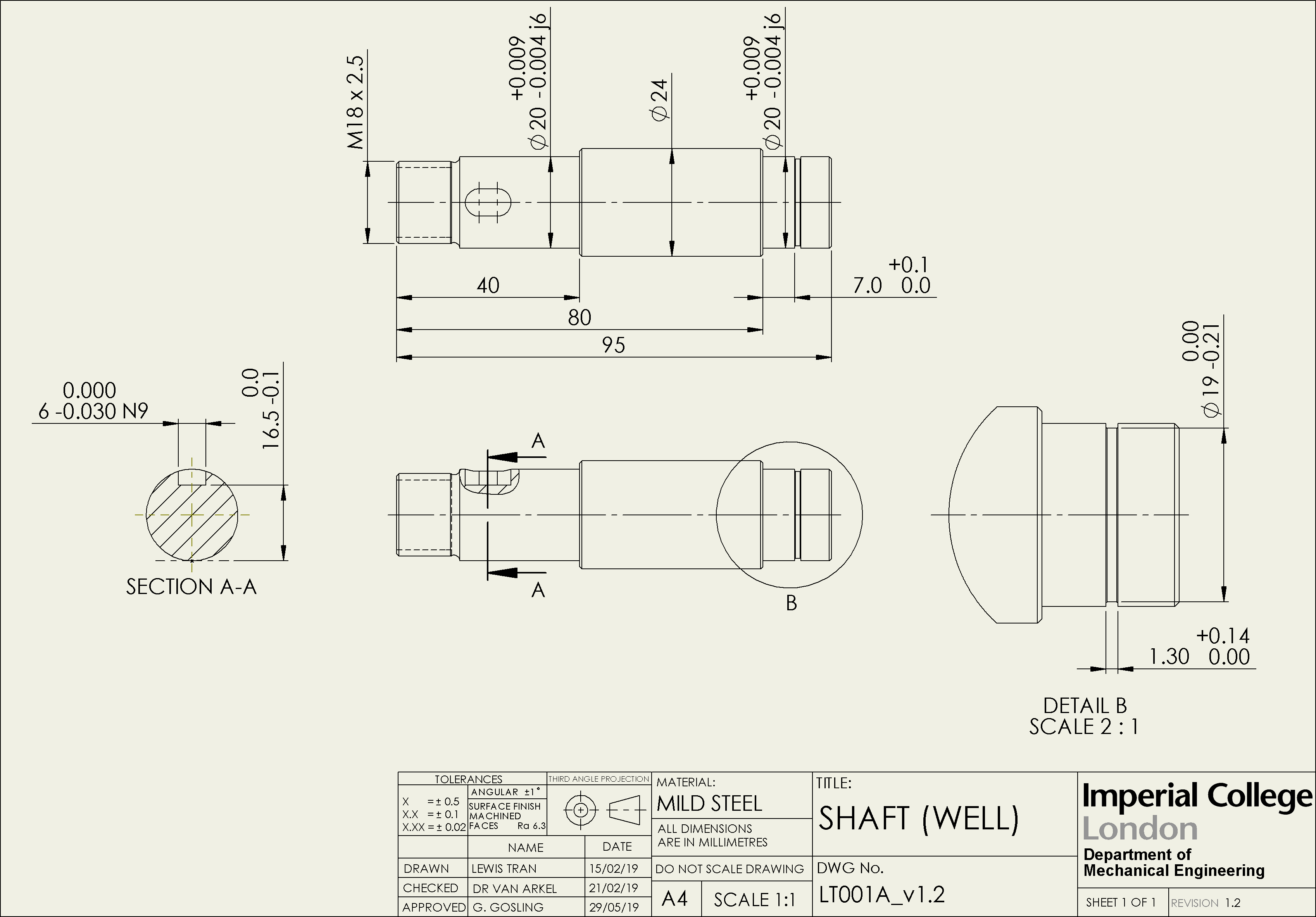
Web geometric dimensioning and tolerancing (gd&t or gd and t) is a language of symbols and standards designed and used by engineers and manufacturers to describe the shape (geometry) and size (dimensions) of a product and facilitate communication between entities working together to manufacture products. Technical drawings often include notations such as “50 g6” or “17.5 h11/g8” to specify tolerances..
Engineering Drawings & GD&T For the Quality Engineer
Technical drawings often include notations such as “50 g6” or “17.5 h11/g8” to specify tolerances. Entry of the tolerances on the drawing. Web tolerancing tolerance is the total amount a dimension may vary and is the difference between the upper (maximum) and lower (minimum) limits. Web the standard is intended to provide uniformity in drawing specifications and interpretation, reducing guesswork.

Examples of Determining the Tolerance on an Engineering Drawing? ED
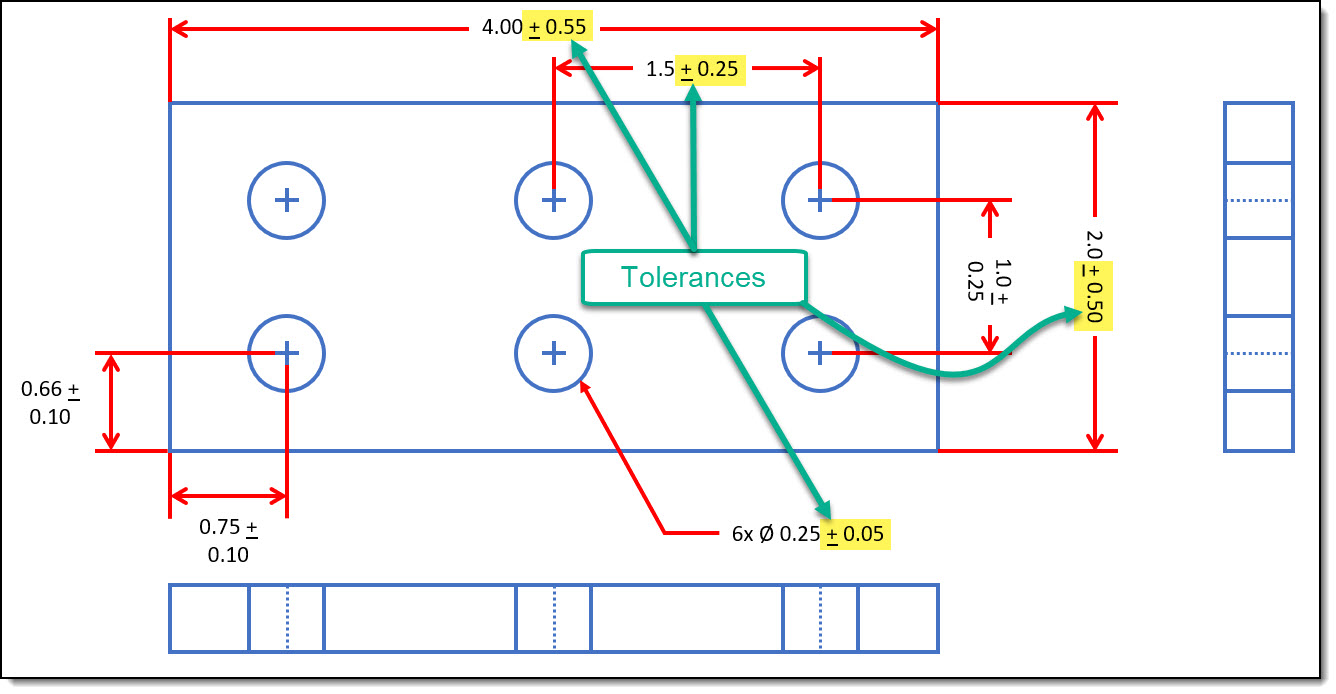
Tolerances are used to control the amount of variation inherent in all manufactured parts. Web engineering tolerances include dimension tolerance, shape tolerance, and position tolerance. Web the standard is intended to provide uniformity in drawing specifications and interpretation, reducing guesswork throughout the manufacturing process. Why does the designer do this? In europe, the standard to follow is.

Tolerances A Brief Introduction EngineeringClicks
Web engineering tolerances include dimension tolerance, shape tolerance, and position tolerance. Tolerances can apply to different units, including voltage, volume, weight, current, temperature, etc. Why does the designer do this? Limitations of tolerancing before gd&t. Web tolerancing tolerance is the total amount a dimension may vary and is the difference between the upper (maximum) and lower (minimum) limits.

GD&T 101 An Introduction to Geometric Dimensioning and Tolerancing
Technical drawings often include notations such as “50 g6” or “17.5 h11/g8” to specify tolerances. Through this method, y14.5 aims to improve quality, lower costs, and shorten deliveries wherever mechanical parts are designed or manufactured. Classification and symbols of geometric tolerance characteristics. And the minimum value is called the minimum dimension. Using gd&t results in a more accurate design, larger.
Types Of Tolerance In Engineering Drawing at GetDrawings Free download
Entry of the tolerances on the drawing. Web tolerance is the total amount a dimension may vary and is the difference between the upper (maximum) and lower (minimum) limits. Web geometric dimensioning and tolerancing (gd&t or gd and t) is a language of symbols and standards designed and used by engineers and manufacturers to describe the shape (geometry) and size.
Engineering Tolerances Design Learning Objects
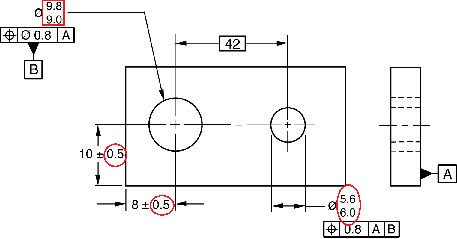
The maximum allowable value is called the maximum dimension. Tolerances are used to control the amount of variation inherent in all manufactured parts. Tolerance in engineering or engineering tolerance is the acceptable variation in a specific measurement from the base measurement or assigned dimensions. True position theory (size value in rectangular frame) However, perfect parts don’t exist in.
Web The Standard Is Intended To Provide Uniformity In Drawing Specifications And Interpretation, Reducing Guesswork Throughout The Manufacturing Process.
Web geometric dimensioning and tolerancing (gd&t) is a system of symbols and standards used in engineering drawings and models to specify the required form, size, orientation, and location of parts and features. Web tolerancing tolerance is the total amount a dimension may vary and is the difference between the upper (maximum) and lower (minimum) limits. A great way to find all the corresponding engineering tolerances to specific measurements is by using a limits & fits calculator. The circularity symbol is used to describe how close an object should be to a true circle.
Web Geometric Dimensioning And Tolerancing (Gd&T Or Gd And T) Is A Language Of Symbols And Standards Designed And Used By Engineers And Manufacturers To Describe The Shape (Geometry) And Size (Dimensions) Of A Product And Facilitate Communication Between Entities Working Together To Manufacture Products.
Gd&t, short for geometric dimensioning and tolerancing, is a system for defining and communicating design intent and engineering tolerances that helps engineers and manufacturers optimally control variations in manufacturing processes. If you take a look at an engineering drawing, you will notice that there are always limits, or tolerances, placed on a dimension. 7.9k views 2 years ago. Because it is impossible to make everything to an exact size, tolerances are used on production drawings to control the parts.
An Engineering Drawing May Include General Tolerances In The Form Of A Table Or Just A Little Note Somewhere On The Drawing (E.g.
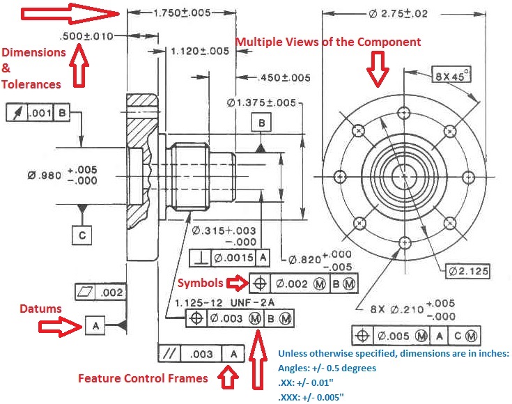
Web geometric tolerances are specified using symbols on a drawing. Web a measured value or physical property of a material, manufactured object, system, or service; Web geometric dimensioning and tolerancing is a set of rules and gd&t symbols used on a drawing to communicate the intent of a design, focusing on the function of the part. Web what is a tolerance?
Entry Of Fit Tolerances On The Engineering Drawing.
True position theory (size value in rectangular frame) It’s the basics of engineering tolerance. Other measured values (such as temperature, humidity, etc.); When a part is designed, the cad model is designed exactly how we want the part to be.