Types Of Electrical Drawings
Types Of Electrical Drawings - Web a few drawings in electrical and electronics engineering are shop drawings, ifcs, schematics, circuit wiring diagrams, ifts, and 3d models. They’re like a map for building or troubleshooting circuits, and can tell you almost everything you need to know to understand how a circuit works. The schematic diagram, also known as a circuit diagram, is the most commonly used type of electrical diagram. These graphical representations showcase control circuits and relay logic in industrial automation systems. Web types of electrical diagrams: Block diagrams provide an overview of the overall system and show the relationship between different components. Ladder diagram or line diagram. Web what is a wiring diagram used for? It uses standardized symbols to depict various components and connections in the circuit. To enable the reader to separate and keep track of each step, each level of successive (sequential) operations from the first action (initiation) to the.
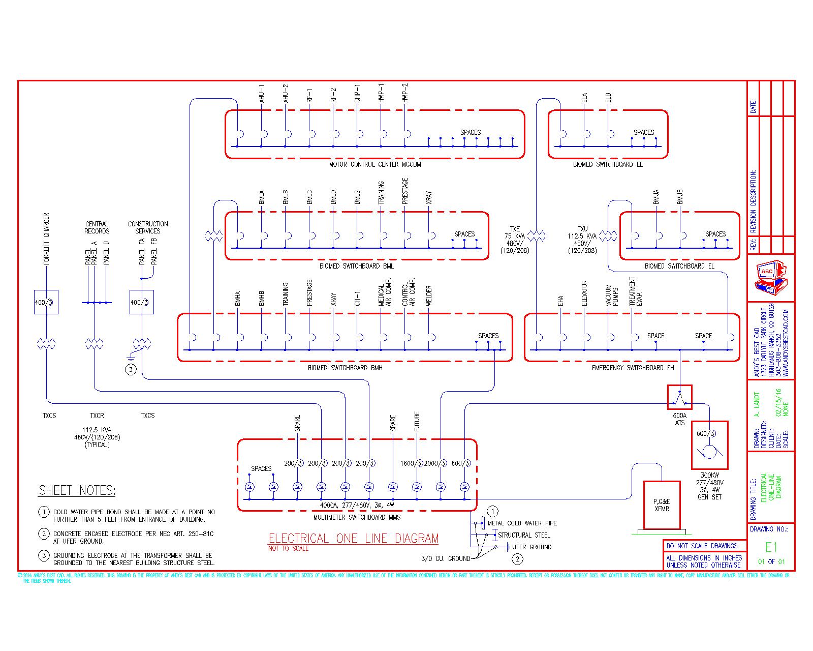
The objective of this segment is to inculcate basic understanding of electrical symbols, electrical drawing conventions and electrical design strategy. Line diagram or ladder diagram. The circuit in which direct current (d.c.) flows is known as the d.c. They are wiring, schematic, and pictorial diagrams. This comprehensive guide will delve into the different types of electrical and electronics engineering drawings, exploring their distinct features, applications, and significance in the industry. Web learn about the distinctions between various diagram types (ladder, schematic, and wiring diagrams) commonly used in electrical engineering: Ladder diagram or line diagram. An electrical drawing is a type of technical drawing that shows information about power, lighting, and communication for an engineering or architectural project. Web what is a wiring diagram used for? This shows all the connections existing between the various elements in an electric installation.
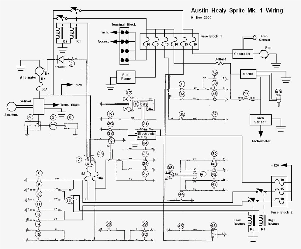
An electrical diagram is a graphical representation of an electrical system property. How to read a wiring diagram. Web electrical drawing preparation do’s & don’ts. Web an electrical schematic is a diagram that shows how all of the wires and components in an electronic circuit are connected. Pictorial diagram (diagram in pictures) 6). This comprehensive guide will delve into the different types of electrical and electronics engineering drawings, exploring their distinct features, applications, and significance in the industry. Web learn about the distinctions between various diagram types (ladder, schematic, and wiring diagrams) commonly used in electrical engineering: The figure represents the d.c. The objective of this segment is to inculcate basic understanding of electrical symbols, electrical drawing conventions and electrical design strategy. Web there are several different types of electrical diagrams, each serving a specific purpose and providing different levels of detail.
Different Types Of Electrical Drawings
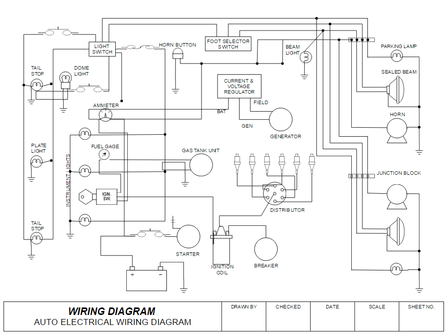
A wiring diagram is a simplified representation of the conductors (wires) and components (devices, lights, motors, switches, sensors and more) that make up an electrical circuit or electrical system. Line diagram or ladder diagram. Web there are several different types of electrical diagrams, each serving a specific purpose and providing different levels of detail. The circuit in which direct current.

different types of electrical drawings Wiring Work
Web different types of electric diagrams. Web what is a wiring diagram used for? To enable the reader to separate and keep track of each step, each level of successive (sequential) operations from the first action (initiation) to the. The schematic diagram, also known as a circuit diagram, is the most commonly used type of electrical diagram. Web outline of.
How to Read and Interpret Electrical Shop Drawings Part Four
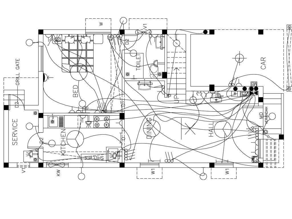
Wiring diagrams show the physical layout and connection of wires and components. An electrical drawing is a type of technical drawing that shows information about power, lighting, and communication for an engineering or architectural project. Web what is a wiring diagram used for? To enable the reader to separate and keep track of each step, each level of successive (sequential).

How to Read Electrical Drawing YouTube
The figure represents the d.c. Web there are several different types of electrical diagrams, each serving a specific purpose and providing different levels of detail. Web different types of electric diagrams. Block diagrams provide an overview of the overall system and show the relationship between different components. Web some of the types of electrical drawings used for any project can.

Electrical Working Drawings An Essential Guide For Electricians In
Web following are the types of electrical circuits with diagram: There are several types of electrical diagrams, including block diagrams, wiring diagrams, and ladder diagrams. This shows all the connections existing between the various elements in an electric installation. The two most commonly used are the wiring diagram and the schematic diagram. Line diagram or ladder diagram.
Electrical Drawing at GetDrawings Free download
Web a few drawings in electrical and electronics engineering are shop drawings, ifcs, schematics, circuit wiring diagrams, ifts, and 3d models. Web there are several different types of electrical diagrams, each serving a specific purpose and providing different levels of detail. Web outline of drawing and drawings. Web basic electrical and electronic graphical symbols called schematic symbols are commonly used.

electrical drawing standards Wiring Diagram and Schematics
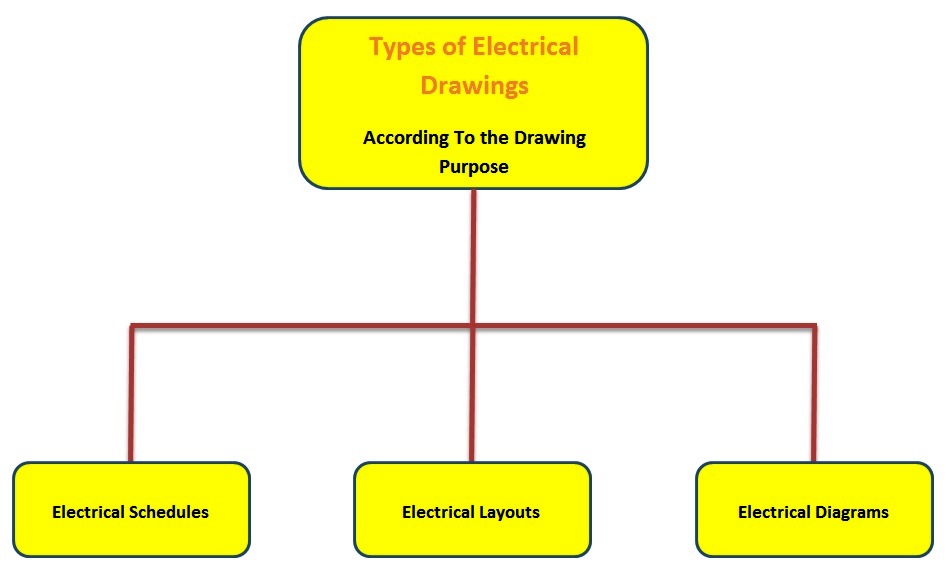
Web some of the types of electrical drawings used for any project can be categorized as block diagrams, layout drawings, single line diagrams, wiring diagrams etc. Line diagram or ladder diagram. An electrical drawing is a type of technical drawing that shows information about power, lighting, and communication for an engineering or architectural project. Web following are the types of.
Electrical Drawing at GetDrawings Free download
A wiring diagram is a simplified representation of the conductors (wires) and components (devices, lights, motors, switches, sensors and more) that make up an electrical circuit or electrical system. Any electrical working drawing consists of lines, symbols, dimensions, and notations to accurately convey an engineering's. Web three common types of electrical drawings are discussed. They’re like a map for building.
How to Draw Electrical Diagrams and Wiring Diagrams
They are wiring, schematic, and pictorial diagrams. What is a wiring diagram? The objective of this segment is to inculcate basic understanding of electrical symbols, electrical drawing conventions and electrical design strategy. January 15, 2024 by david peterson. Ladder diagram or line diagram.

Understanding Electrical Drawings Part 1 YouTube
A wiring diagram is the most basic type of electrical diagram. Web some of the types of electrical drawings used for any project can be categorized as block diagrams, layout drawings, single line diagrams, wiring diagrams etc. These graphical representations showcase control circuits and relay logic in industrial automation systems. It uses standardized symbols to represent components, such as resistors..
Web Following Are The Types Of Electrical Circuits With Diagram:
Web three common types of electrical drawings are discussed. It uses standardized symbols to depict various components and connections in the circuit. The schematic diagram, also known as a circuit diagram, is the most commonly used type of electrical diagram. Web learn about the distinctions between various diagram types (ladder, schematic, and wiring diagrams) commonly used in electrical engineering:
Electrical Drawings, Schematics, And Wiring Diagrams:
Web basic electrical and electronic graphical symbols called schematic symbols are commonly used within circuit diagrams, schematics and computer aided drawing packages to identify the position of individual components and elements within a circuit. They are wiring, schematic, and pictorial diagrams. What is a wiring diagram? Web different types of electric diagrams.
Wiring Diagrams Show The Physical Layout And Connection Of Wires And Components.
Ladder diagram or line diagram. Web types of electrical diagrams: Web electrical symbols and electronic circuit symbols are used for drawing schematic diagram. To enable the reader to separate and keep track of each step, each level of successive (sequential) operations from the first action (initiation) to the.
A Wiring Diagram Is The Most Basic Type Of Electrical Diagram.
Electrical diagrams and schematics 9 types of electrical diagrams or schematics there are three ways to show electrical circuits. Web there are several types of electrical diagrams, each serving a specific purpose and providing valuable information about the system. Web some of the types of electrical drawings used for any project can be categorized as block diagrams, layout drawings, single line diagrams, wiring diagrams etc. Web what is a wiring diagram used for?