Types Of Lines In Engineering Drawing
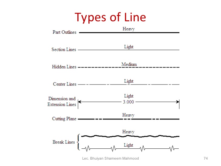
Types Of Lines In Engineering Drawing - Drawing usually means using drawing instruments, from compasses to computers to bring precision to the drawings. Break lines are used to represent a long object or feature that is too large to be shown in its entirety on a drawing. An extension line extends a line on the object to the. The standard line types used in technical drawings are center. Web in addition to line type, line width is also an important factor in conveying information on an engineering drawing. Center lines are thin, alternating long and short dashes that are generally used to show hole centers and center positions of rounded features, such as arcs and radii. Sketching generally means freehand drawing. We will treat sketching and drawing as one. A visible line, or object line is a thick continuous line, used to outline the visible edges or contours of an object. The most common is a continuous line, also known as a drawing line.
Engineering drawings and sketches need to display simplicity and uniformity, and they must be executed with speed. That is, the length is roughly three times the width. For example, on a drawing with a scale of 1:10 or larger, the minimum width for solid lines is 0.6 mm, while the minimum width for. By kelly curran glenn sokolowski. The most common is a continuous line, also known as a drawing line. The alphabet of lines and the approximate dimensions used to create different line types, are referred to as linestyles when used with cad. Not every line on an engineering drawing is equal. Web the alphabet of lines is a set of standard line types established by the american national standards institute (ansi) for technical drawing. Web different types of lines. Bs 8888:2008 technical product specification.
That is, the length is roughly three times the width. They provide measurements that define the length, width, height, or diameter of objects, allowing for accurate replication and manufacturing. Object lines stand out on the drawing and clearly define the outline and features of the object. The alphabet of lines and the approximate dimensions used to create different line types, are referred to as linestyles when used with cad. For example, on a drawing with a scale of 1:10 or larger, the minimum width for solid lines is 0.6 mm, while the minimum width for. The most important ones include solid lines (representing visible edges or boundaries of objects), dashed lines (indicating hidden or invisible parts behind other elements), dotted lines (used for centerlines or symmetry), and thin lines (for. The final drawings are drafted with pencil, are generally divided into 2 line groups. Web lines on mechanical engineering drawings 1 scope this part of iso 128 specifies general rules and basic conventions for the types of lines on mechanical engineering drawings. Center lines are thin, alternating long and short dashes that are generally used to show hole centers and center positions of rounded features, such as arcs and radii. Web the purpose of this guide is to give you the basics of engineering sketching and drawing.
Theory of Line Types Types of Lines in Engineering Drawing 3.0
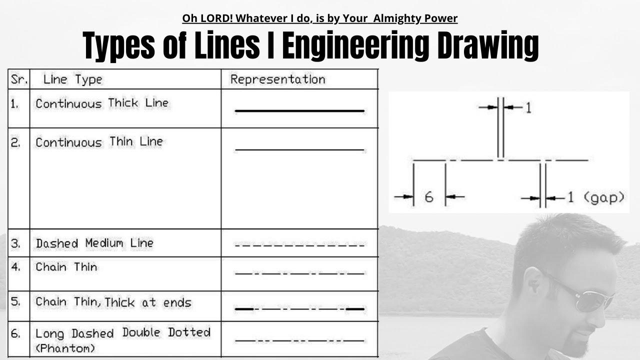
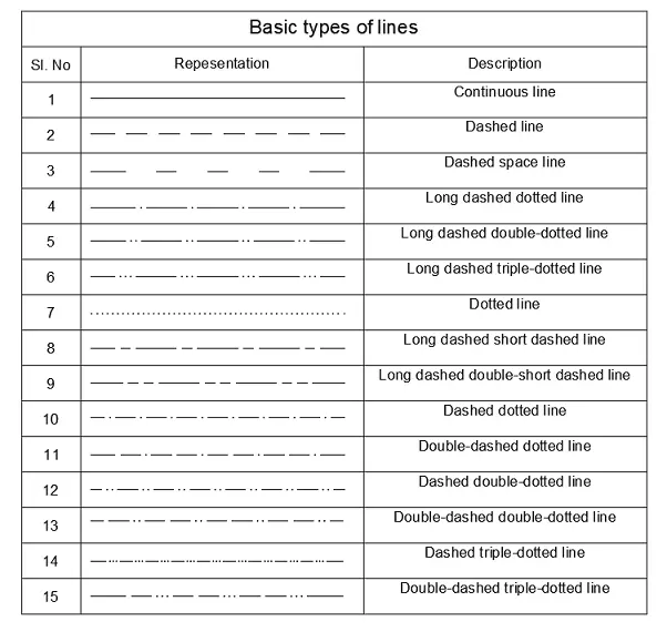
Center lines (figure \(\pageindex{5}\)) are used in drawings for several different applications. Engineering drawing has evolved into a language that uses an. They are 0.6 mm thick. Dimension lines are drawn as continuous, thin lines with arrowheads at each end. Following are the different types of lines used in engineering drawing:
ENGINEERING DRAWING Lines
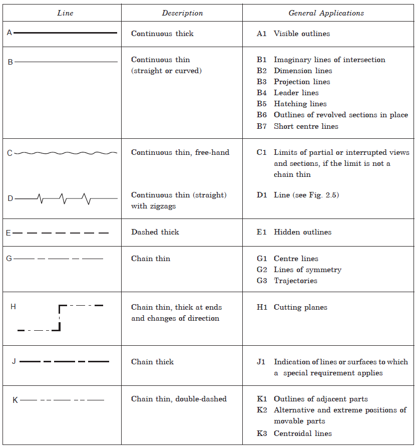
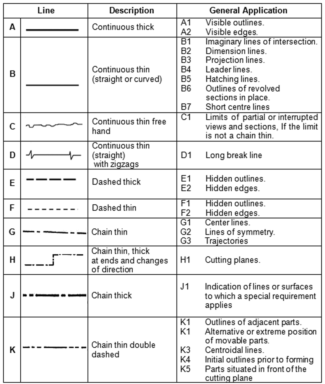
Web in addition to line type, line width is also an important factor in conveying information on an engineering drawing. Web the line types for engineering drawing as recommended by bis are as follows. Web lines on mechanical engineering drawings 1 scope this part of iso 128 specifies general rules and basic conventions for the types of lines on mechanical.

Types Of Lines In Engineering Drawing And Their Uses
Engineering drawing has evolved into a language that uses an. Web the dashed line may be either thick or thin, but only one type (thick or thin) should be used on a single drawing or set of drawings. The standard line types used in technical drawings are center. The construction lines should be thin and faint. Web the dimension line.
Engineering Drawing 8 Tips to Improve Engineering Drawing Skills
The purpose of engineering drawings is to convey objective facts, whereas artistic drawings convey emotion or artistic sensitivity in some way. Sketching generally means freehand drawing. Engineering drawing has evolved into a language that uses an. Web lines on mechanical engineering drawings 1 scope this part of iso 128 specifies general rules and basic conventions for the types of lines.

What are Lines & Types Of Lines in Engineering Drawing ? YouTube
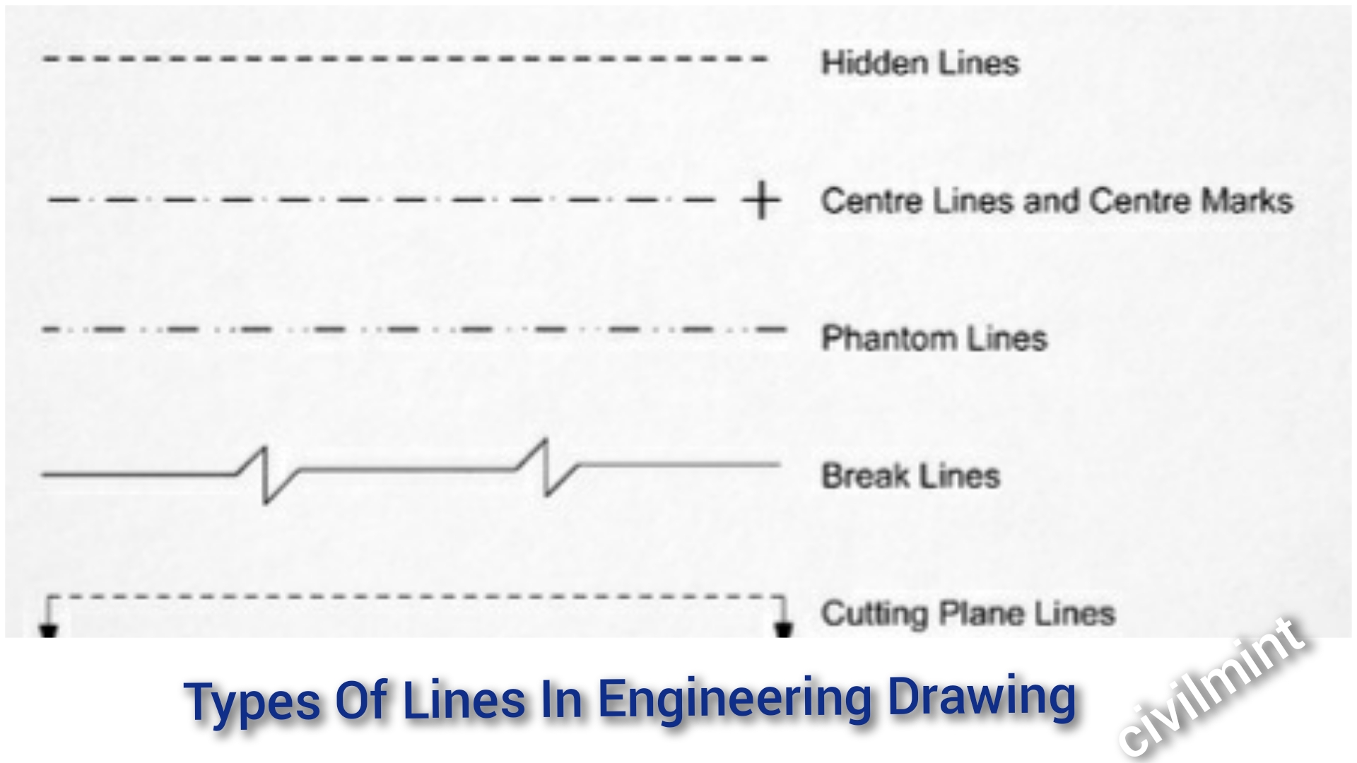
These are various types of lines commonly used in technical drawings, engineering, and architectural drafting: Web the dashed line may be either thick or thin, but only one type (thick or thin) should be used on a single drawing or set of drawings. In this highly interactive object, learners associate basic line types and terms with engineering drawing geometry. Dimension.
Types Of Lines In Drawing at Explore collection of
An arrowhead is approximately 3 mm long and 1 mm wide. Engineering drawing has evolved into a language that uses an. The most important ones include solid lines (representing visible edges or boundaries of objects), dashed lines (indicating hidden or invisible parts behind other elements), dotted lines (used for centerlines or symmetry), and thin lines (for. Following are the different.

10 Different Types of Lines Used In Engineering Drawing
A quiz completes the activity. Bs 8888:2008 technical product specification. The most important ones include solid lines (representing visible edges or boundaries of objects), dashed lines (indicating hidden or invisible parts behind other elements), dotted lines (used for centerlines or symmetry), and thin lines (for. An arrowhead is approximately 3 mm long and 1 mm wide. Web lines on mechanical.

INCH Technical English pictorial engineering drawing line types
A hidden line, also known as a hidden object line is a medium weight line, made of short dashes about 1/8” long with 1/16”gaps, to show edges, surfaces and corners which cannot be seen. Web types of lines explained with following timestamp: Bs 8888:2008 technical product specification. Center lines (figure \(\pageindex{5}\)) are used in drawings for several different applications. Hidden.
Types Of Line In Engineering No.1 Detailed Guide To Line Types
Web the line types for engineering drawing as recommended by bis are as follows. Break lines are used to represent a long object or feature that is too large to be shown in its entirety on a drawing. Hidden lines are 0.3 mm thin dashed line. Web the new ipad pro — the thinnest apple product ever — features a.
Types Of Lines In Engineering Drawing
Once again, you are free to make up your own line definitions, but it is recommended that you put a note on the drawing with their meaning. Often this line is used as a point of reference on engineering drawings. Bs 8888:2008 technical product specification. Not every line on an engineering drawing is equal. Web in addition to line type,.
Web The Dashed Line May Be Either Thick Or Thin, But Only One Type (Thick Or Thin) Should Be Used On A Single Drawing Or Set Of Drawings.
We will treat sketching and drawing as one. Once again, you are free to make up your own line definitions, but it is recommended that you put a note on the drawing with their meaning. Bs 8888:2008 technical product specification. Hidden lines are 0.3 mm thin dashed line.
Center Lines Are Thin, Alternating Long And Short Dashes That Are Generally Used To Show Hole Centers And Center Positions Of Rounded Features, Such As Arcs And Radii.
These thick, solid lines show the visible edges, corners, and surfaces of a part. The most common is a continuous line, also known as a drawing line. Web the line types for engineering drawing as recommended by bis are as follows. The most important ones include solid lines (representing visible edges or boundaries of objects), dashed lines (indicating hidden or invisible parts behind other elements), dotted lines (used for centerlines or symmetry), and thin lines (for.
They Are 0.6 Mm Thick.
It is very essential to maintain all the drawing lines except construction lines should be uniform, clean, and dense. For example, on a drawing with a scale of 1:10 or larger, the minimum width for solid lines is 0.6 mm, while the minimum width for. The final drawings are drafted with pencil, are generally divided into 2 line groups. Web in addition to line type, line width is also an important factor in conveying information on an engineering drawing.
Not Every Line On An Engineering Drawing Is Equal.
Line weight on a drawing varies from a thin line to a thicker line. An extension line extends a line on the object to the. Following are the different types of lines used in engineering drawing: The thin chain line is used to indicate center lines, the lines of symmetry and also trajectories.