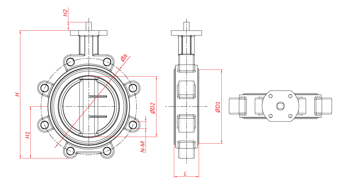
Valve Drawing
Valve Drawing - Web what is a piping & instrumentation diagram (p&id)? Web our product range catalogue: Web learn about types of valve symbols used in p&id and iso drawing. Web vci (valve control illustrated) specializes in valve control assembly cad valve drawings, actuator drawing and 3d models. Web to provide 2d drawings of valves, etc. Web a piping and instrumentation diagram (p&id) is a graphic representation of a process system that includes the piping, vessels, control valves, instrumentation, and other process components and equipment in the system. Such as ball valve, plug valve, refile valve, gate valve, check valve, butterfly valve. Web in each process and instrumentation diagram, valves have specific symbols that make them easy to recognize. For use by consulting engineers in the preparation of layouts and plan details. Web learn about valves symbols used in p&id and piping isometric drawings.
View technical drawings of rotary valves by acs valves here. Figure 1 shows the symbols that depict the major valve types. Web isometric drawing symbols for piping valves. Web in this article, you will learn what is flow control valves? It should be noted that globe and gate valves will often be depicted by the same valve symbol. Web learn about valves symbols used in p&id and piping isometric drawings. Web what is a piping & instrumentation diagram (p&id)? Here is a list of symbols for various types of valves used in process industry. Visit our cad drawings page to download a drawing into 66 different file formats, including autocad, revit, solidworks and step. Can’t figure out why your machinery isn’t performing?
Web in each process and instrumentation diagram, valves have specific symbols that make them easy to recognize. Need someone to scratch your nose for you while you work? Therefore, the valves are used to regulate the fluid’s flow and pressure within a system. It should be noted that globe and gate valves will often be depicted by the same valve symbol. Valve controls system or process fluid flow and pressure by performing any of the following functions: A valve is a device comprising of an obturator or closure member that is used to control flow or pressure in a piping system. This version of internet explorer is either no longer supported by microsoft , or is obsolete and some features of our store may no longer be supported. The symbol typically consists of the actual valve symbol, and the actuation method such as pneumatic, hydraulic, or electric. Figure 1 shows the symbols that depict the major valve types. Jacketed ball valve, full & half jacketed.
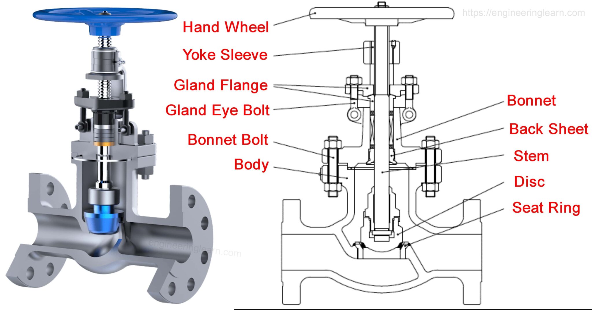
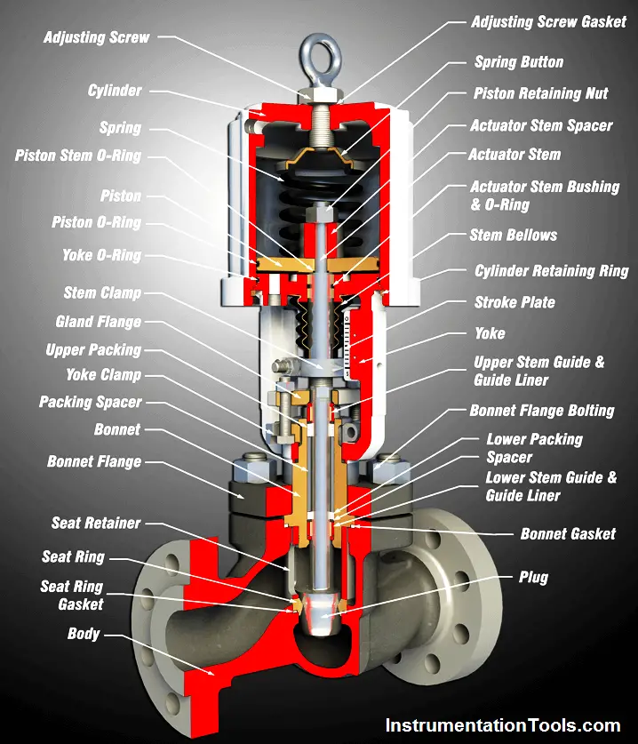
Flow Control Valve Definition, Types, Components & Working Principle
Check out our user manuals, tech support videos, articles, and faq’s below, or call our tech support, paul, for more help. Web a piping and instrumentation diagram (p&id) is a graphic representation of a process system that includes the piping, vessels, control valves, instrumentation, and other process components and equipment in the system. It should be noted that globe and.
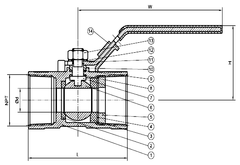
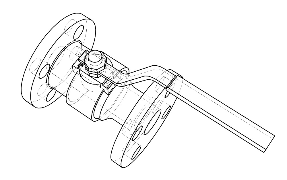
ball valve 2d cad drawing Valve ball bibliocad
This version of internet explorer is either no longer supported by microsoft , or is obsolete and some features of our store may no longer be supported. Web to provide 2d drawings of valves, etc. Therefore, the valves are used to regulate the fluid’s flow and pressure within a system. A p&id is a detailed, visual representation of a process.

Full Welded Body Ball Valve Dynamic Drawing 2 Production Valves
Web a piping and instrumentation diagram (p&id) is a graphic representation of a process system that includes the piping, vessels, control valves, instrumentation, and other process components and equipment in the system. Valve controls system or process fluid flow and pressure by performing any of the following functions: Web to provide 2d drawings of valves, etc. Web cad drawings make.
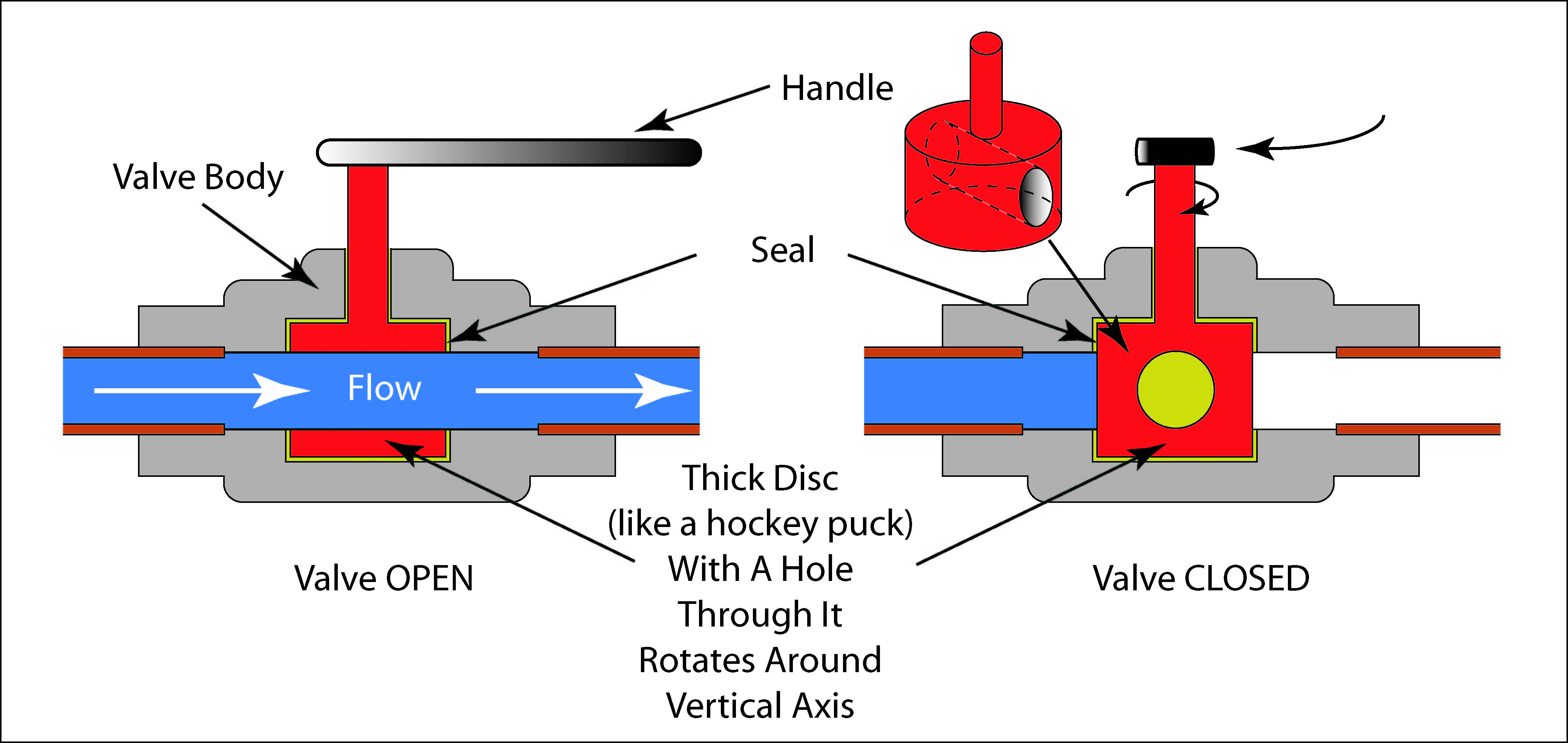
Basic Parts of Control Valves Control Valve Functions Valve Parts
Web introduction to vendor drawing review. Want some info on how to replace your shaft seal? For use by consulting engineers in the preparation of layouts and plan details. Web a basic understanding of the differences between the various types of valves, and how these differences affect valve function, will help ensure the proper application of each valve type during.
![Gate Valve 3D Model DWG [ Drawing Free ] in AutoCAD for Architect.](https://dwgfree.com/wp-content/uploads/2021/02/Gate-Valve-3D-dwg-in-autocad-drawing.jpg)
Gate Valve 3D Model DWG [ Drawing Free ] in AutoCAD for Architect.
Visit our cad drawings page to download a drawing into 66 different file formats, including autocad, revit, solidworks and step. We have been in business for over 25 years serving the valve control industry. Web valve diagrams, therefore, play a significant role in interpreting p&ids by denoting the type of valves used, their operation, inlet, center position, and functional process.
Gate valve detail 3d model sketchup file Cadbull
Web by mastering the foundational lexicon of valve symbols, we empower our stakeholders to navigate the complexities of valve selection, application, and maintenance with unparalleled confidence. View technical drawings of rotary valves by acs valves here. Such as ball valve, plug valve, refile valve, gate valve, check valve, butterfly valve. We have been in business for over 25 years serving.
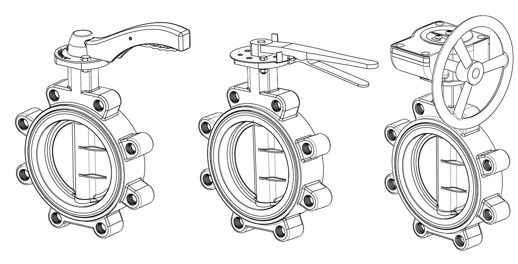
Understanding the Basics of Downloading a Butterfly Valve Drawing
Vendor drawing review (vdr) is a review of valve drawings indicating cross sectional view, material of construction with respect to purchase requisition (pr)requirements / data sheets. The instruments’ function within a process. Web in this article, you will learn what is flow control valves? Web learn about types of valve symbols used in p&id and iso drawing. Web cad drawings.
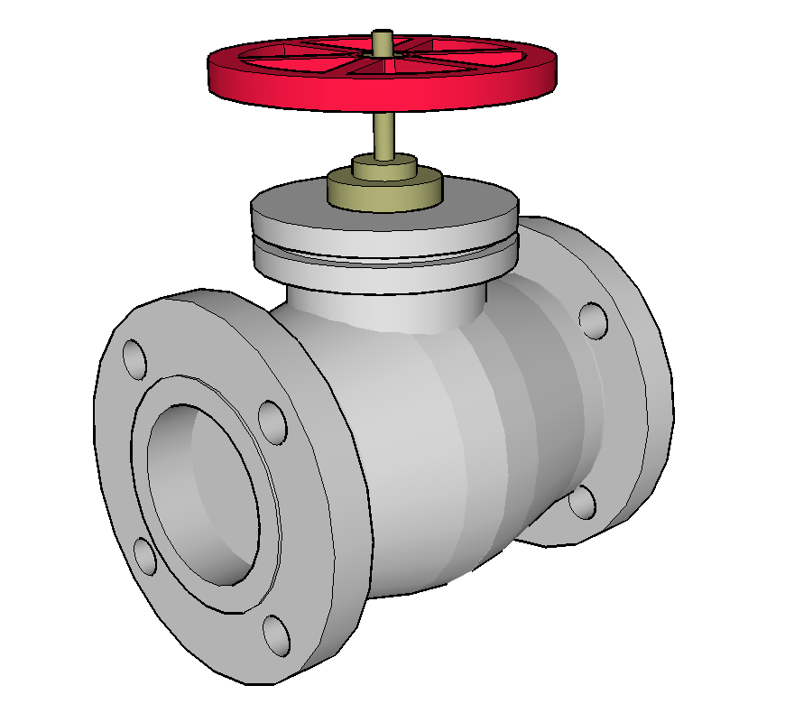
Valves Manual Valves Ball, Rotary and Piston Valves CTG Technical
Web a piping and instrumentation diagram (p&id) is a graphic representation of a process system that includes the piping, vessels, control valves, instrumentation, and other process components and equipment in the system. Web by mastering the foundational lexicon of valve symbols, we empower our stakeholders to navigate the complexities of valve selection, application, and maintenance with unparalleled confidence. Web a.
Understanding the Basics of Downloading a Butterfly Valve Drawing
We have been in business for over 25 years serving the valve control industry. Web our product range catalogue: Their parts, working, types, and uses are explained with pictures & pdf. Web learn about types of valve symbols used in p&id and iso drawing. Web type of valve employed depends on nature of fluid, flow control required, operating pressure and.
Types of Valves and Their Applications and Selection Criteria
View technical drawings of rotary valves by acs valves here. Web valve is a mechanical device that controls the flow of fluid and pressure within a system or process. Web the complex world of process and instrumentation drawings (p&ids) is replete with a range of valve diagrams and symbols. Jacketed ball valve, full & half jacketed. Here is a list.
Therefore, The Valves Are Used To Regulate The Fluid’s Flow And Pressure Within A System.
Can’t figure out why your machinery isn’t performing? Web valve is a mechanical device that controls the flow of fluid and pressure within a system or process. Web a basic understanding of the differences between the various types of valves, and how these differences affect valve function, will help ensure the proper application of each valve type during design and the proper use of each valve type during operation. A valve is a device comprising of an obturator or closure member that is used to control flow or pressure in a piping system.
Web In Simple Terms, A Valve Is An Internal Component That Controls And Regulates The Flow Of Fluid In A System By Closing, Opening, Or Partially Cutting Off The Flow Of A Fluid For Various Reasons.
The instruments’ function within a process. Web introduction to vendor drawing review. Web technical drawings of rotary valves | acs valves. Web vci (valve control illustrated) specializes in valve control assembly cad valve drawings, actuator drawing and 3d models.
Web In This Article, You Will Learn What Is Flow Control Valves?
A p&id is a detailed, visual representation of a process system. Visit our cad drawings page to download a drawing into 66 different file formats, including autocad, revit, solidworks and step. Web valve diagrams, therefore, play a significant role in interpreting p&ids by denoting the type of valves used, their operation, inlet, center position, and functional process flow graphics diagram. Web to provide 2d drawings of valves, etc.
Such As Ball Valve, Plug Valve, Refile Valve, Gate Valve, Check Valve, Butterfly Valve.
Here is a list of symbols for various types of valves used in process industry. Web cad drawings make incorporating dezurik valves into a piping layout at the design stage quick and easy. Web the complex world of process and instrumentation drawings (p&ids) is replete with a range of valve diagrams and symbols. Jacketed ball valve, full & half jacketed.