Weld Callouts On Drawings
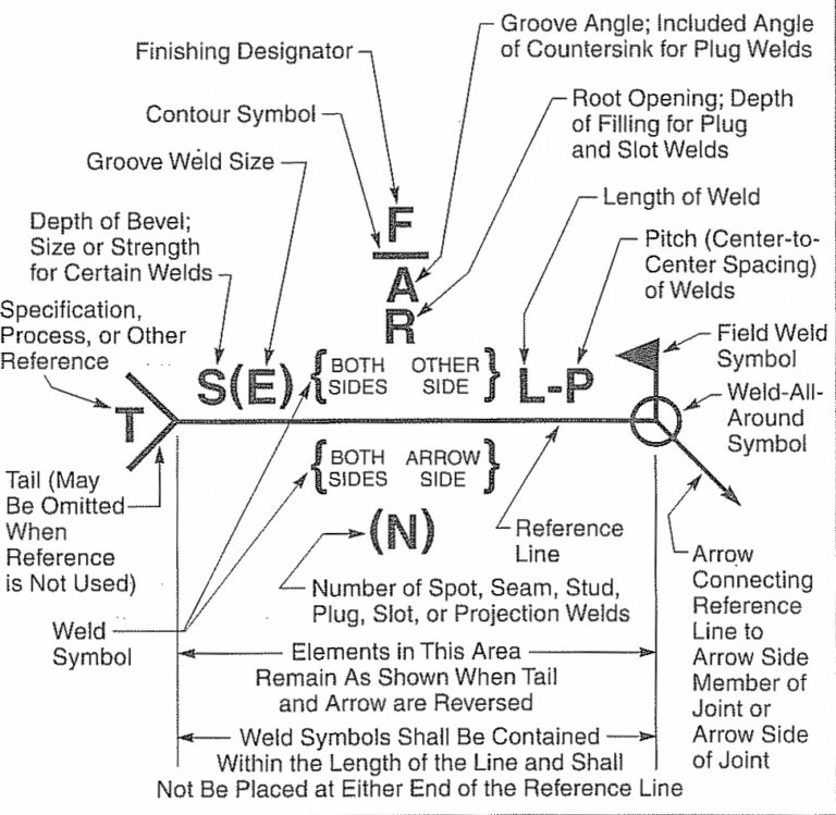
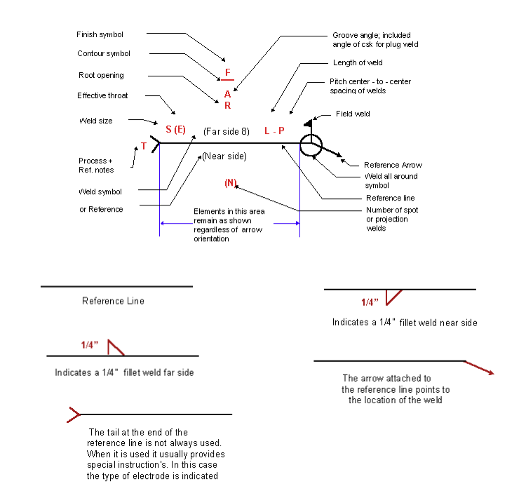
Weld Callouts On Drawings - You will often find these on engineering and fabrication drawings. Web weld symbols come with an arrow that points to the direction of the drawing where a weld needs to be made. These are placed on either side of the weld symbol or above it, specifying the size, length or pitch of the weld. These callouts will be found on the technical drawings (or blueprint) of the assembly, also known as a weldment, and will specify weld geometry and its associated. The welding symbol is made of several parts including the reference line, arrow, and weld symbol when required. The objective of this specification is to ensure welds of proper quality, and to ensure the safety, quality and serviceability of the product without increasing cost or fabrication time. Web a weld callout (a grouping of weld symbols informing the interpreter of the entire joint welding process) includes weld symbols and any other relevant information all standardized on a leader arrow. These sit on the arrow or the other side of the reference line, indicating the type of weld. Web welding symbols are the integral part and the basic requirements for fabrication as they provide vital information for the welding joint location, weld size (throat or leg length, depth of penetration) & length, weld type & quality requirements for the fabrication or construction drawing. Web when using an intermittent weld there is a call out specified for the length of the weld and also the pitch that is to be applied.
You will often find these on engineering and fabrication drawings. Web weld symbols come with an arrow that points to the direction of the drawing where a weld needs to be made. Web welding symbols are the integral part and the basic requirements for fabrication as they provide vital information for the welding joint location, weld size (throat or leg length, depth of penetration) & length, weld type & quality requirements for the fabrication or construction drawing. Web when using an intermittent weld there is a call out specified for the length of the weld and also the pitch that is to be applied. Here we will introduce you to the common symbols and their meaning. These are symbols used to indicate welding methods, weld form, and weld size, among other technical content on a drawing. When this is shown on the right side of the symbol and it is called as the length of segment a hyphen and then the pitch of the welds. Web welding symbols are used to indicate desired welding & brazing details on the fabrication drawings. The standard creo welding symbol libraries provide general ansi and iso welding symbols. Web 11 process and method.
These are placed on either side of the weld symbol or above it, specifying the size, length or pitch of the weld. The arrow line is connected to a leader line which is intersected with a horizontal reference line. These are symbols used to indicate welding methods, weld form, and weld size, among other technical content on a drawing. Learn how to interpret and use weld callout symbols and notations effectively in your projects. Web when using an intermittent weld there is a call out specified for the length of the weld and also the pitch that is to be applied. You can easily customize and create new welding symbols to. Web detailed part drawings may contain many welding symbols. Web a set of symbols are shorthand for describing the type of weld, its size, and other processing and finishing information. Click annotate > show model annotations. The library symbols are the default symbols.
How to Read Welding Blueprints Like a Pro
This designation is a letter callout and it commonly follows the first letter of the process name. Web welding symbols are used to indicate desired welding & brazing details on the fabrication drawings. The show model annotations dialog box opens. Web weld symbols come with an arrow that points to the direction of the drawing where a weld needs to.
Weld Symbols On Drawings
Relevant tabs become available in the show model annotations dialog box. In the model tree, select the weld whose symbol you want to show. Learn how to interpret and use weld callout symbols and notations effectively in your projects. The use of symbols can significantly reduce the time needed to complete a drawing compared to drawing the weld as it.

Weld Symbols
Web having said that (above) there are usually phrases in the contract documents that when a welding symbol is missing or even other information, if you are sure of the application and have other similar joint/weld points on other shop or erection drawings you can do them the same. It consists of several elements that convey essential information to the.

Welding Symbols Guide And Chart Fillet and Groove Weld
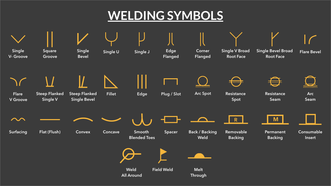
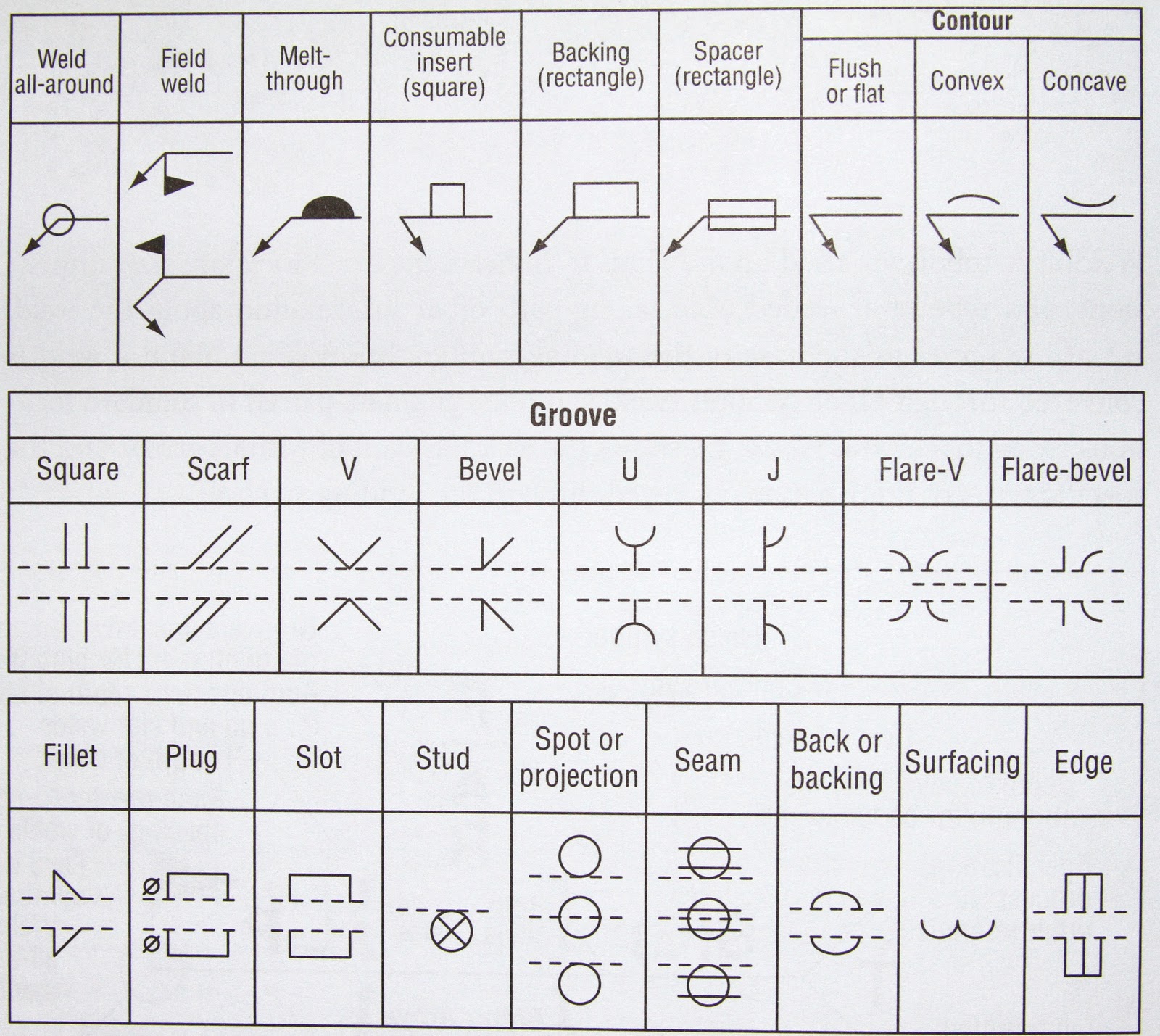
Here we will introduce you to the common symbols and their meaning. The use of symbols can significantly reduce the time needed to complete a drawing compared to drawing the weld as it will appear. Web a set of symbols are shorthand for describing the type of weld, its size, and other processing and finishing information. These are symbols used.
Welding Symbols Explained
This designation is a letter callout and it commonly follows the first letter of the process name. These are symbols used to indicate welding methods, weld form, and weld size, among other technical content on a drawing. Web a spot weld is simple a weld applied to the surface of one member that has enough heat input to melt into.
Weld Symbols With Examples Design Talk
Web the stitch welding symbol is a graphical representation used on engineering drawings to specify the stitch weld pattern required for a particular joint. Web a weld callout (a grouping of weld symbols informing the interpreter of the entire joint welding process) includes weld symbols and any other relevant information all standardized on a leader arrow. When this is shown.

Welding Symbols with Figures PAKTECHPOINT
Web 11 process and method. Web a set of symbols are shorthand for describing the type of weld, its size, and other processing and finishing information. Web when using an intermittent weld there is a call out specified for the length of the weld and also the pitch that is to be applied. Learn how to interpret and use weld.
Understanding the Welding Symbols in Engineering Drawings Safe Work
Web 11 process and method. Web basic weld symbols: These are symbols used to indicate welding methods, weld form, and weld size, among other technical content on a drawing. For example flux cored arc welding is fcaw. When this is shown on the right side of the symbol and it is called as the length of segment a hyphen and.

Understanding the Basic Welding Symbols
The library symbols are the default symbols. It is essential that everyone should have a full understanding of weld symbol requirements to ensure that the initial design requirement is met. Web having said that (above) there are usually phrases in the contract documents that when a welding symbol is missing or even other information, if you are sure of the.
Printable Weld Symbol Chart
Here we will introduce you to the common symbols and their meaning. The weld symbol specifies the type of weld to be applied to a part. Web 11 process and method. For example flux cored arc welding is fcaw. Web basic weld symbols:
For Example Flux Cored Arc Welding Is Fcaw.
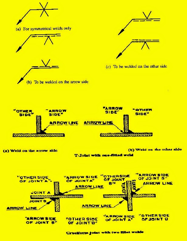
Web subcontractors are often required to interpret weld symbols on engineering drawings, from perhaps the main contractor or client to determine the type of weld needed. An example of arrow side spot weld and a no side significance resistance spot weld below. Web definition of welding symbols. Web when designing parts for general metal fabrication, welding symbols, and detailed callouts will be required to communicate design intent and requirements effectively to manufacturers.
The Weld Symbol Specifies The Type Of Weld To Be Applied To A Part.
The pitch of the weld is measured as center to center of the next segment. The welding symbol is a graphical representation that is used to give the design requirements to the shop in a concise manner. You will often find these on engineering and fabrication drawings. Web using welding symbols to indicate necessary welding information on engineering drawings offers several advantages:
You Can Easily Customize And Create New Welding Symbols To.
These are placed on either side of the weld symbol or above it, specifying the size, length or pitch of the weld. Web 11 process and method. The objective of this specification is to ensure welds of proper quality, and to ensure the safety, quality and serviceability of the product without increasing cost or fabrication time. Web about welding symbols in drawings.
The Welding Symbol Is Made Of Several Parts Including The Reference Line, Arrow, And Weld Symbol When Required.
The show model annotations dialog box opens. When this is shown on the right side of the symbol and it is called as the length of segment a hyphen and then the pitch of the welds. This was a very basic introduction to weld symbols. There are a lot of processes in the welding industry, in order to streamline the call out of these there are letter designations for them.