Weld Symbols In Drawings
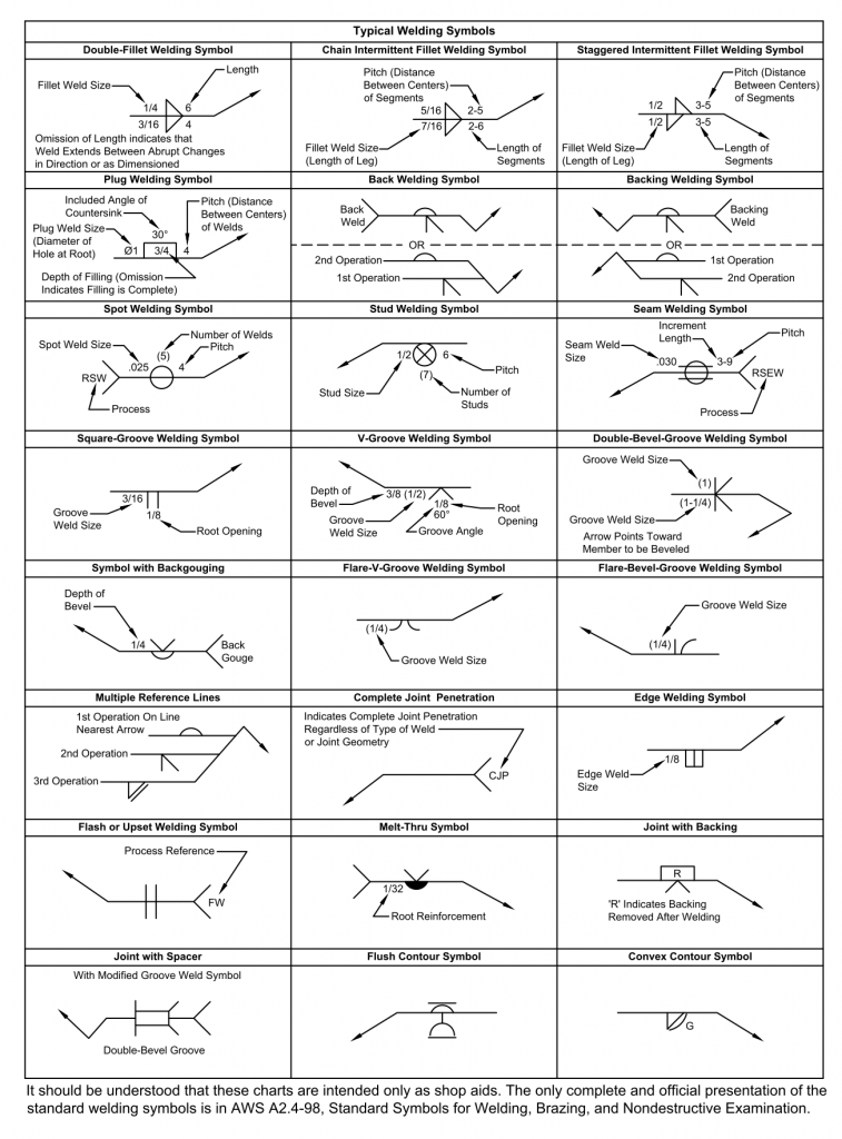
Weld Symbols In Drawings - Web the 9 steps below represent a very basic introduction to welding symbols. If the welds are symmetrical on both sides of the plate the dashed. Whenever two or more pieces are joined by welding, the assembled item is called a. They allow precise communication of the. However, it is also important that shop floor personnel are able to read and understand the details of weld symbols. Instead of using an arrow and saying ‘weld here’, a weld symbol carries more useful information that can be easily understood by the welder, engineer, foreman, supervisor and architect. The major difference between the american and british standard are given below. Basic weld symbol the weld symbol always includes 1. Complete weld representation methods consist of the basic symbol, auxiliary symbol, supplementary symbol, leader, dimension symbol, and data. If you have a questions please let us know by replying to the post.
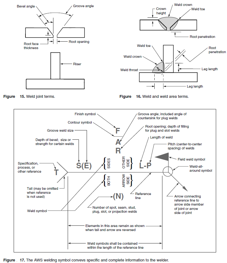
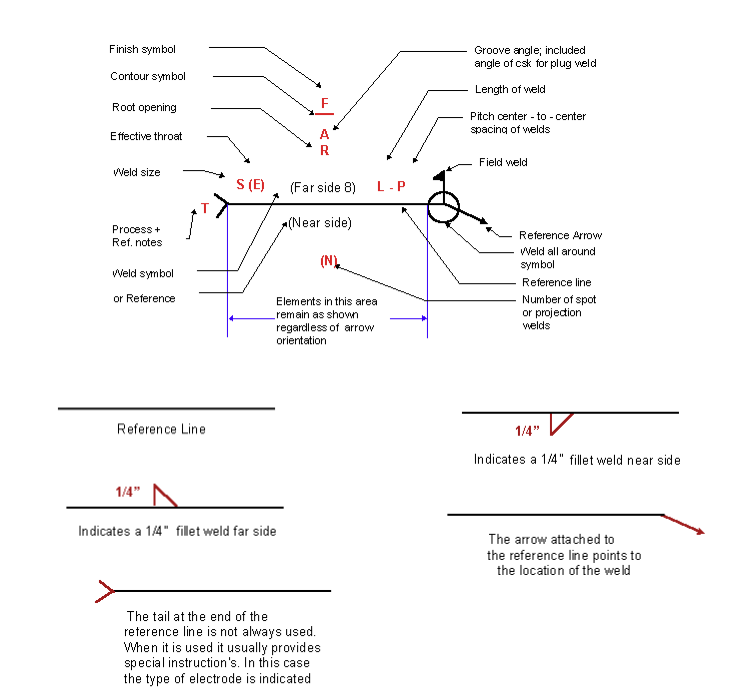
The open circle at the arrow/reference line junction indicates a weld is to go all around the joint, as in the example below. Instead of using an arrow and saying ‘weld here’, a weld symbol carries more useful information that can be easily understood by the welder, engineer, foreman, supervisor and architect. The welding symbol is made of several parts including the reference line, arrow, and weld symbol when required. Hence, welding symbols are widely used in engineering drawings by. A symbol can be used to specify the weld type, groove design, welding process, face & root contour,. Every weld symbol must consist of an arrow and a reference line. Web sometimes drawings are very full, so this rule is necessary in case there is no room for the base symbol to be on the side the weld is. Web during metal joining processes, weld symbols are meant to indicate different parts of the process. Since the symbols are standardized, they provide consistency across different drawings, irrespective of who the designer or the welder is. Web welding symbols are used to indicate desired welding & brazing details on the fabrication drawings.
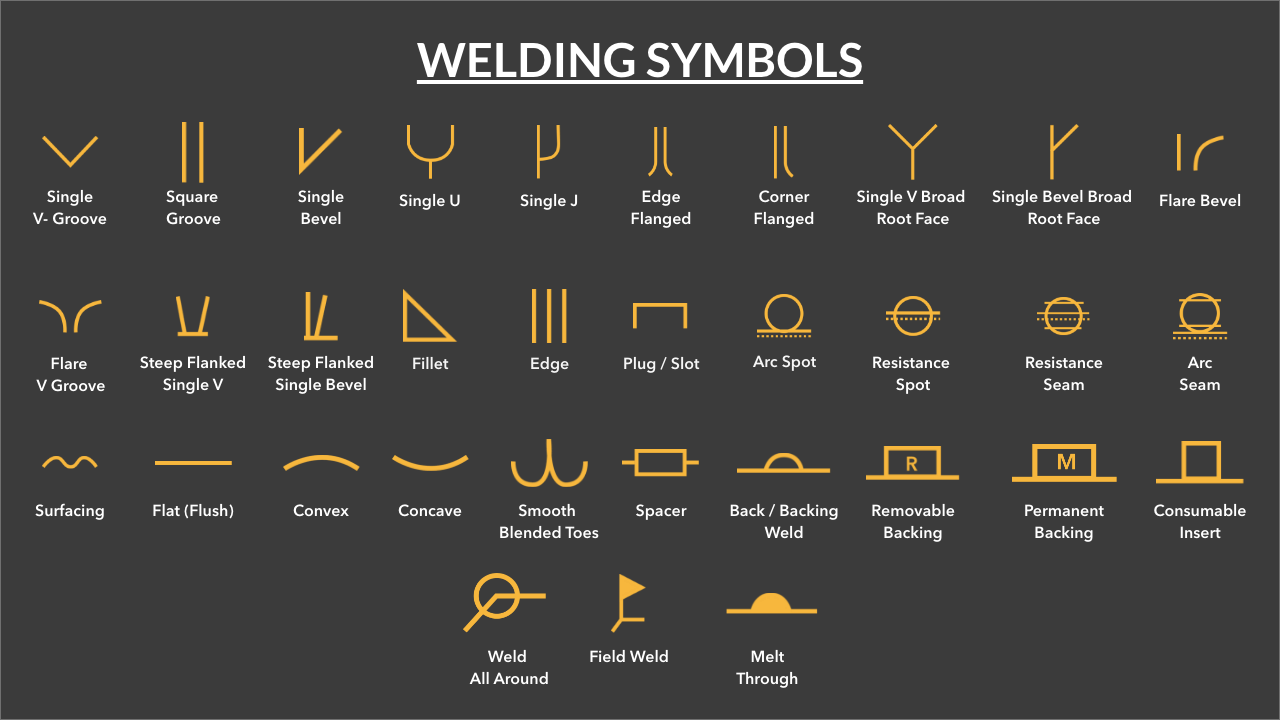
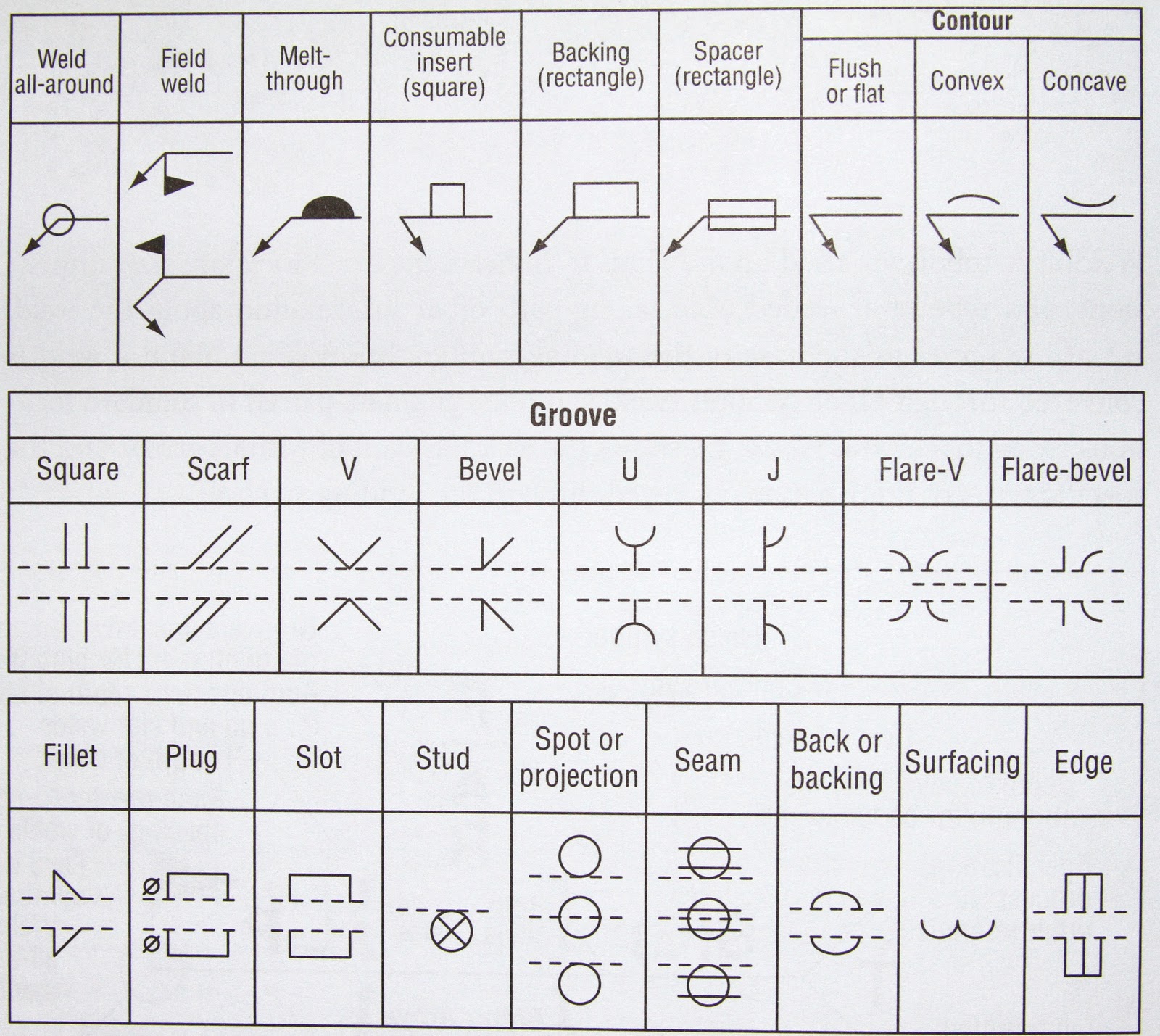
A welding symbol uses ‘ weld symbols ‘ to convey. Base system b here, when the welding symbol is on the underside of the reference line, the weld is. Web welding symbols, also referred to as weld callouts and welding drawing symbols, contain information pertinent to the weld as previously mentioned. Hence, welding symbols are widely used in engineering drawings by. A welding symbol is what you see on the fabrication drawing. It is essential that the 'rules' of the standard used are correctly applied by drawing office personnel. Web there are two major standards for weld symbols aws a2.4 (american standard) and bs en 2554 ( british standard). Web weld symbols are a key part of welding documentation, and understanding how to read weld symbols is critical for welders. Web sometimes drawings are very full, so this rule is necessary in case there is no room for the base symbol to be on the side the weld is. These sit on the arrow or the other side of the reference line, indicating the type of weld.;
Printable Welding Symbols Chart Printable World Holiday
Web understanding welding symbol placement. These sit on the arrow or the other side of the reference line, indicating the type of weld.; Web the entire symbol, with all of its numbers and other symbols, is called the welding symbol. The placement of welding symbols in blueprint drawings is not arbitrary. These symbols are usually found in fabrication and engineering.
How to Read Welding Blueprints Like a Pro
When identification of the weld process is required as part of the weld symbol the relevant weld process code is listed in bs en iso 4063. Web the weld symbols are always placed on the reference line of the welding symbol. Web welding symbols are a graphical way to convey information about a welding joint. Web there are two major.
Welding Terms and Symbols Basic welding symbols Engineersfield
These sit on the arrow or the other side of the reference line, indicating the type of weld.; The open circle at the arrow/reference line junction indicates a weld is to go all around the joint, as in the example below. If the welds are symmetrical on both sides of the plate the dashed. Web sometimes drawings are very full,.

chapter 18 welding joint design welding symbols and fabrication
These standards have been through numerous revisions over the last few years; Weld symbols on the dashed line relates to weld on the far side of the plate. Weld symbols on the full reference line relates to welds on the near side of the plate being welded. This is where the symbols sit.; The welding symbol is made of several.
Weld Symbols Chart American Welding Society DWG file Autodesk_AutoCAD
It communicates the location of welding, the type of welding, and all the other details required by the fabricator to execute the fabrication. These sit on the arrow or the other side of the reference line, indicating the type of weld.; Welding symbols are used on drawings of parts and assemblies that are joined together by welding. It is essential.
Understanding the Welding Symbols in Engineering Drawings Safe Work
The symbols in this book are a representation of what weld and welding symbols look like. Web a weld symbol without a flag indicates that the weld is to be made in the shop. Instead of using an arrow and saying ‘weld here’, a weld symbol carries more useful information that can be easily understood by the welder, engineer, foreman,.

Understanding the Basic Welding Symbols
There are three main elements to a weld symbol: Below is a comprehensive list of what one can expect to see on a welding symbol, as well as an example image and list of options for each aspect of the welding symbol. Web sometimes drawings are very full, so this rule is necessary in case there is no room for.

Weld Symbols Explained Design Talk
These symbols are usually found in fabrication and engineering drawings. Weld symbols on the full reference line relates to welds on the near side of the plate being welded. A symbol can be used to specify the weld type, groove design, welding process, face & root contour,. The leader line is composed of an arrow leader line (also known as.

Welder’s Guide to Welding Symbols PrimeWeld
Weld symbols on the full reference line relates to welds on the near side of the plate being welded. The placement of welding symbols in blueprint drawings is not arbitrary. Instead of using an arrow and saying ‘weld here’, a weld symbol carries more useful information that can be easily understood by the welder, engineer, foreman, supervisor and architect. The.
Basic Welding Symbols Weld My World
Web welding symbols are used to indicate desired welding & brazing details on the fabrication drawings. Web weld symbols are a key part of welding documentation, and understanding how to read weld symbols is critical for welders. Web the weld symbols are always placed on the reference line of the welding symbol. It communicates the location of welding, the type.
Web Weld Symbols Are A Key Part Of Welding Documentation, And Understanding How To Read Weld Symbols Is Critical For Welders.
These symbols are usually found in fabrication and engineering drawings. However, each element of the welding symbol has its specified location. Web the 9 steps below represent a very basic introduction to welding symbols. The arrow attached to the reference line points towards the joint or area of the workpiece where the weld is intended.
Since The Symbols Are Standardized, They Provide Consistency Across Different Drawings, Irrespective Of Who The Designer Or The Welder Is.
Welding symbols are used on drawings of parts and assemblies that are joined together by welding. Weld symbols are a very useful way of communicating welding requirements from the design office to the shop floor. There are specific design requirements when used in accordance to a blueprint. Whenever two or more pieces are joined by welding, the assembled item is called a.
The Leader Line Is Composed Of An Arrow Leader Line (Also Known As An Arrow Line) And A Datum Line, Which Can Be Either A Solid.
Instead of using an arrow and saying ‘weld here’, a weld symbol carries more useful information that can be easily understood by the welder, engineer, foreman, supervisor and architect. The welding symbol is a graphical representation that is used to give the design requirements to the shop in a concise manner. Older drawings may denote a field weld by a filled black circle at the junction between the arrow and reference line. This is where the symbols sit.;
The Open Circle At The Arrow/Reference Line Junction Indicates A Weld Is To Go All Around The Joint, As In The Example Below.
The reference line is a horizontal line that is used to align the other elements of the symbol. There are three main elements to a weld symbol: They allow precise communication of the. Web during metal joining processes, weld symbols are meant to indicate different parts of the process.