What Is A Pid Drawing
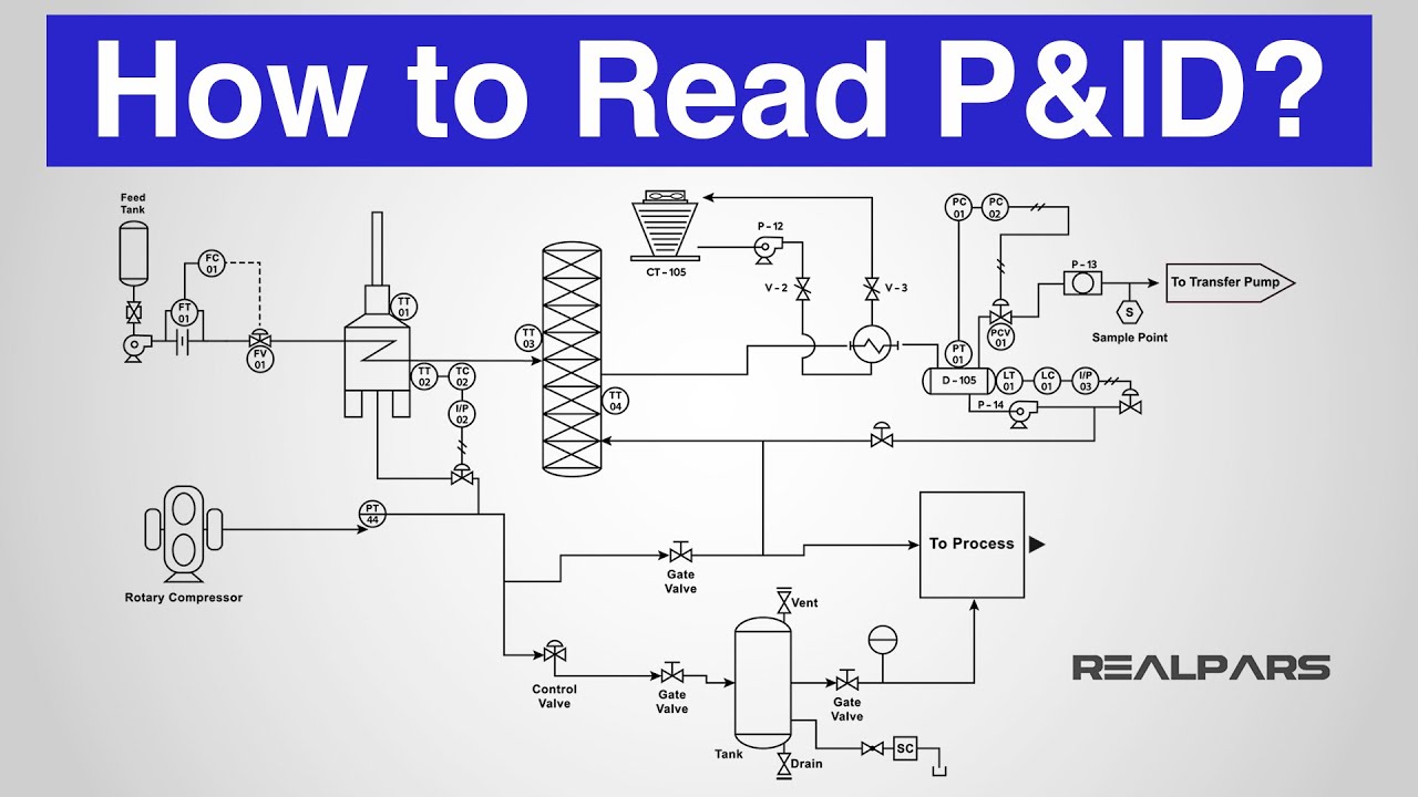
What Is A Pid Drawing - Web what is p&id? It uses symbols to represent process equipment such as sensors and controllers. Web p&id drawing, or piping and instrumentation diagrams, is like a special map that shows how pipes and instruments work together in factories and plants. They offer a detailed overview of the process flow, including equipment, valves, and instrumentation, crucial for design and operational. Web p&id diagrams (piping and instrumentation diagrams) provide a schematic representation of the functional relationship between piping, instrumentation, and system components within a project. Here you can find what information is contained on a p&id. It shows the equipment used in the process, and all of the signals required to measure and control the process. Web a piping and instrumentation diagram (p&id) is a comprehensive schematic that illustrates the functional relationship of piping, instrumentation, and system equipment components within a process plant. Web want to draw piping and instrumentation diagrams? Web how to read p&id drawing easily.
Here you can find what information is contained on a p&id. Create yours using lucidchart for free when you sign up! All valves and their identifications. It uses symbols to represent process equipment such as sensors and controllers. Web p&id diagrams (piping and instrumentation diagrams) provide a schematic representation of the functional relationship between piping, instrumentation, and system components within a project. As the name suggests the graphical representation on a p&id includes all piping connected between equipment's and the associated instrumentation necessary to design,. As said earlier, it is more complex than pfd. 357k views 3 years ago basic instrumentation through. These symbols can represent actuators, sensors, and controllers and may be apparent in most, if not all, system diagrams. Through a p&id, you can get the following information:
P&id is short for “piping and instrumentation diagram”. The p & id includes every mechanical aspect of the plant except stream flows, pipe routing, pipe lengths, pipe fittings, supports, structure & foundations. This information is displayed in the areas surrounding the graphic portion of the drawing. Piping & instrumentation diagram explained. In this video, you will learn. With download pdf for free. Web what is p&id? Web p&id is a graphical representation of the actual process plant using various symbols that represent actual equipment. Web piping and instrumentation diagram (p&id) is a schematic representation of a process flow between all process units or equipment's in a plant. They offer a detailed overview of the process flow, including equipment, valves, and instrumentation, crucial for design and operational.

P & ID Diagram. How To Read P&ID Drawing Easily. Piping
A single pfd can have multiple p&ids. Web what is a p&id drawing? Here you can find what information is contained on a p&id. Web p&id diagrams (piping and instrumentation diagrams) provide a schematic representation of the functional relationship between piping, instrumentation, and system components within a project. Web what is p&id?
How to Read a P&ID? (Piping & Instrumentation Diagram) YouTube
As the name suggests the graphical representation on a p&id includes all piping connected between equipment's and the associated instrumentation necessary to design,. Web p&id drawing, or piping and instrumentation diagrams, is like a special map that shows how pipes and instruments work together in factories and plants. They offer a detailed overview of the process flow, including equipment, valves,.
What is Piping and Instrumentation Diagram (P&ID) ? Inst Tools
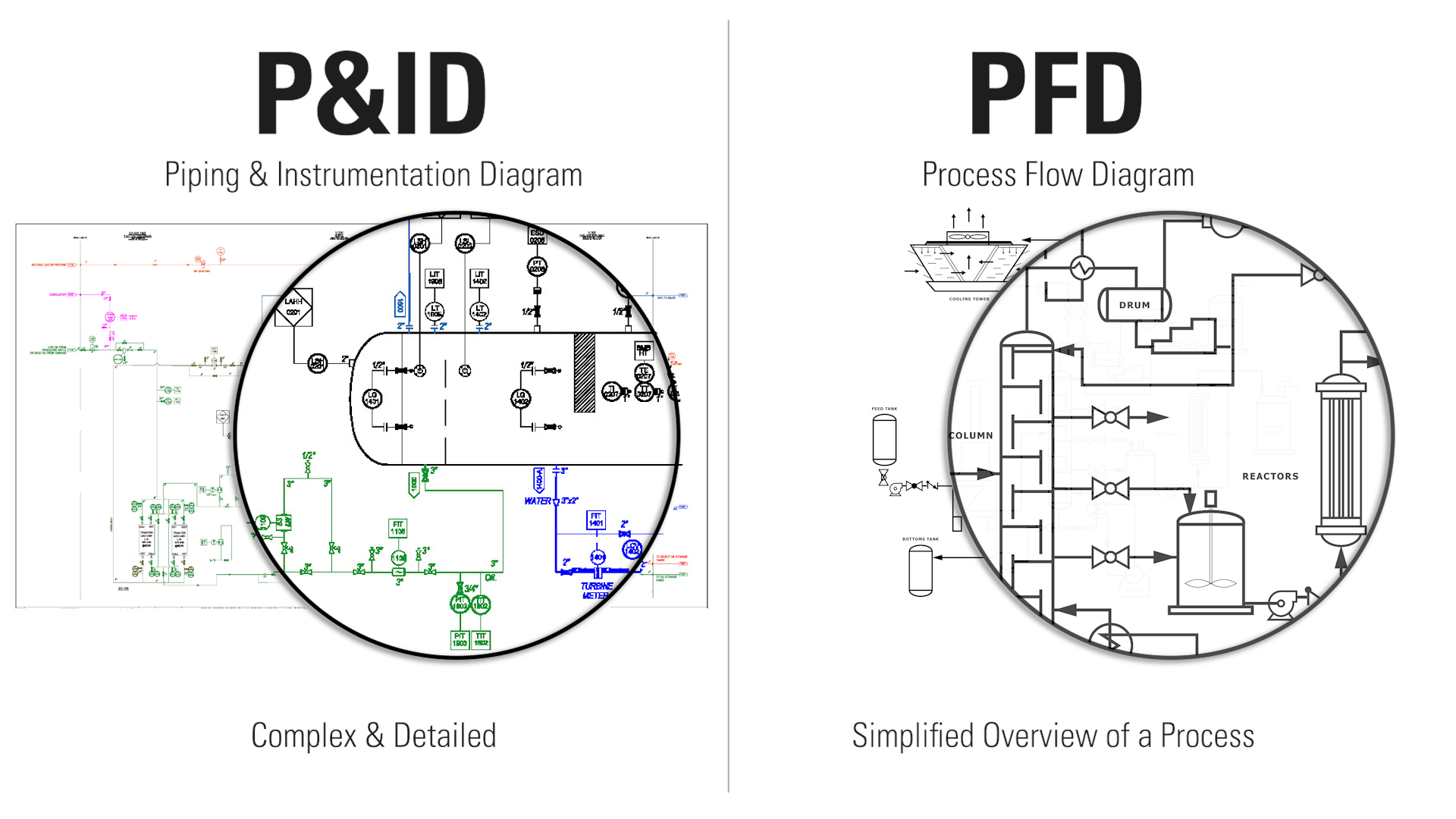
Piping and instrumentation diagrams, or p&ids, are used to create important documentation for process industry facilities. Web how to read p&id drawing easily. A single pfd can have multiple p&ids. Create yours using lucidchart for free when you sign up! It is also called as mechanical flow diagram (mfd).
Learn How to Read P&ID Drawings A Complete Guide
It uses symbols to represent process equipment such as sensors and controllers. As said earlier, it is more complex than pfd. It shows the equipment used in the process, and all of the signals required to measure and control the process. These symbols can represent actuators, sensors, and controllers and may be apparent in most, if not all, system diagrams..

How to Read and Interpret Piping and Instrumentation Diagrams (P&ID
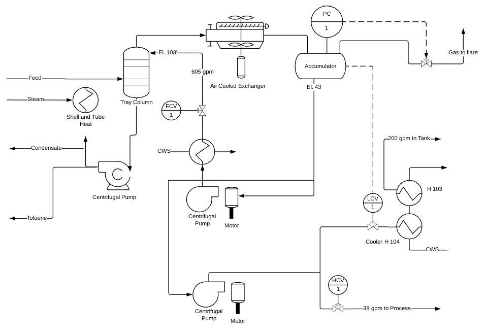
Create yours using lucidchart for free when you sign up! As said earlier, it is more complex than pfd. Web a process and instrumentation diagram (p & id) shows the process flow and interconnection of process equipment which is used control a process. Piping and instrumentation diagrams, or p&ids, are used to create important documentation for process industry facilities. It.
How to Read P&ID Drawing A Complete Tutorial YouTube
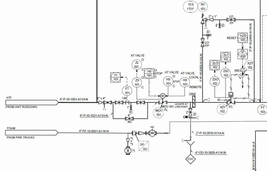
This information is displayed in the areas surrounding the graphic portion of the drawing. Create yours using lucidchart for free when you sign up! Piping and instrumentation diagrams, or p&ids, are used to create important documentation for process industry facilities. It includes all piping, instruments, valves, and equipment the system consists of. Through a p&id, you can get the following.
How to Read Oil and Gas P&ID Symbols Kimray
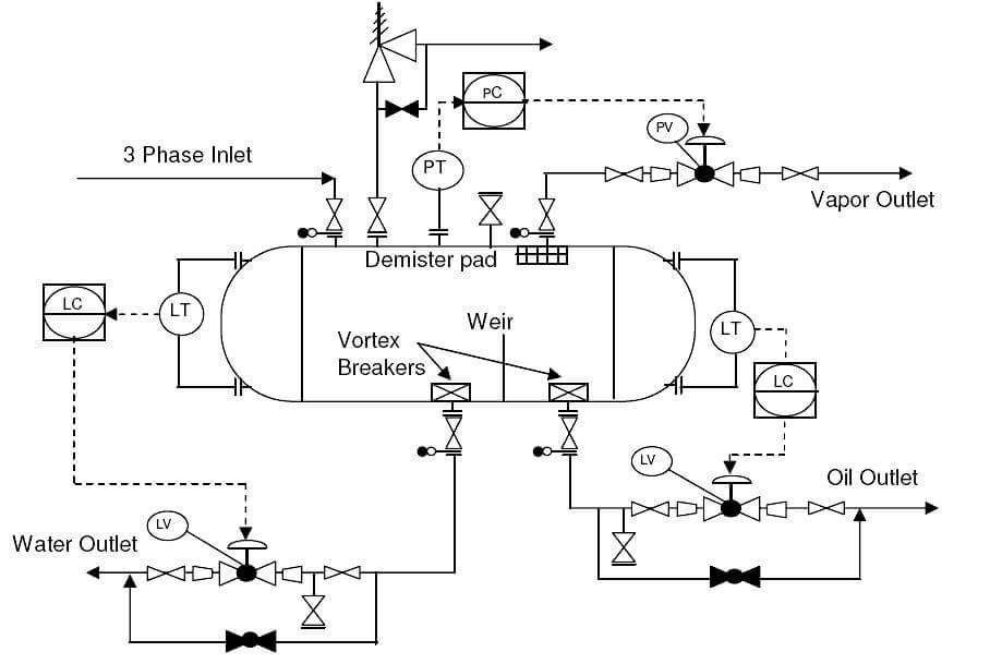
Web a piping and instrumentation diagram displays the piping components (for example equipment, valves, reducers and so on) of an actual physical process flow and is often used in the engineering projects, such as setting up steam boilers, heat exchangers, electric boilers and more. Process piping, sizes and identification. It’s most commonly used in the engineering field. In this video,.
What is a P&ID Beginner’s Guide (2022)
Web piping and instrumentation diagram (p&id) is a schematic representation of a process flow between all process units or equipment's in a plant. Web what is a p&id drawing? A p&id uses simple graphics to represent complex processes and convey the flow of material through a process. Function and purpose of p&ids. It shows the equipment used in the process,.
What is P&ID? (Piping and Instrumentation Diagram)? Synergy Codes
Web a piping and instrumentation diagram displays the piping components (for example equipment, valves, reducers and so on) of an actual physical process flow and is often used in the engineering projects, such as setting up steam boilers, heat exchangers, electric boilers and more. All valves and their identifications. It’s most commonly used in the engineering field. P&id (piping and.

Learn How to Read P&ID Drawings A Complete Guide (2023)
It is also called as mechanical flow diagram (mfd). Web what is p&id? P&id (piping and instrumentation diagram or drawing) is a technical drawing used in process engineering. This information is displayed in the areas surrounding the graphic portion of the drawing. Web a piping and instrumentation diagram, also called p&id, is a diagram used to show a graphical display.
As The Name Suggests The Graphical Representation On A P&Id Includes All Piping Connected Between Equipment's And The Associated Instrumentation Necessary To Design,.
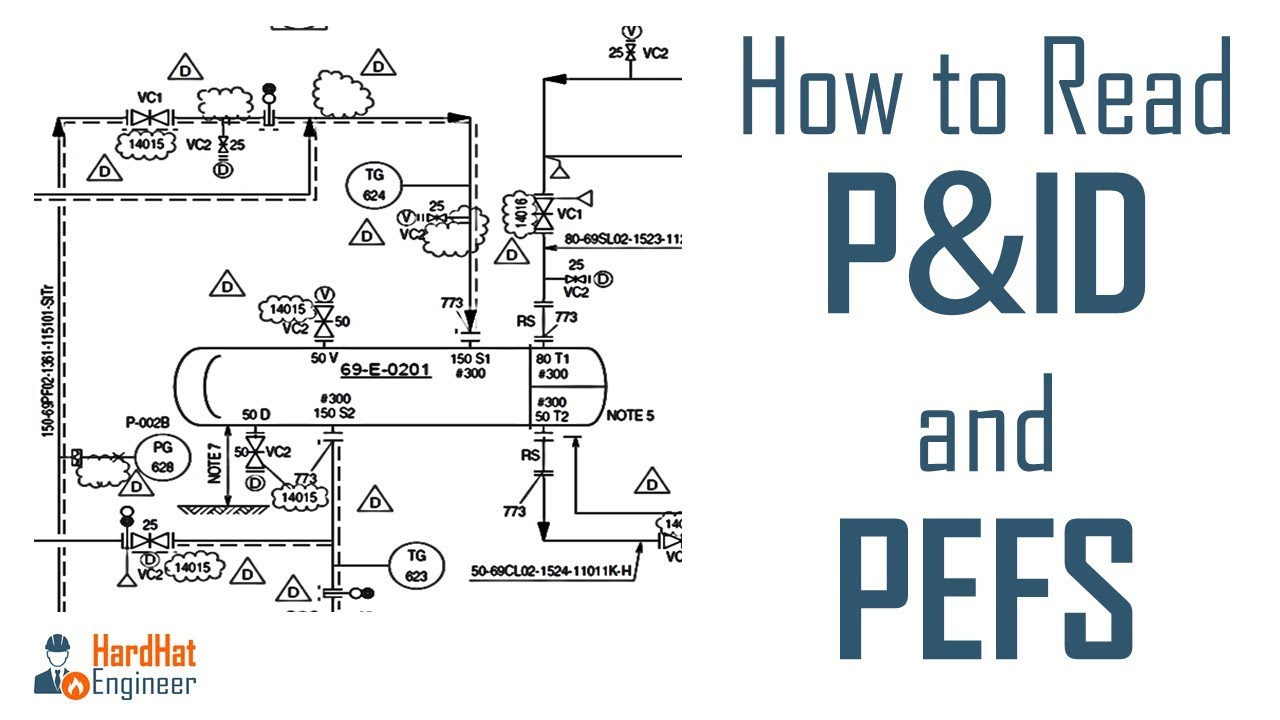
It is the basic training document to explain the process details to operation guys, field engineers, and maintenance professionals. P&id drawing is a schematic representation of instrumentations, control systems, and pipelines used in any process development plant. Piping and instrumentation diagrams, or p&ids, are used to create important documentation for process industry facilities. It uses symbols to represent process equipment such as sensors and controllers.
A P&Id Uses Simple Graphics To Represent Complex Processes And Convey The Flow Of Material Through A Process.
Web what is p&id? Web piping and instrumentation diagram (p&id) is a schematic representation of a process flow between all process units or equipment's in a plant. It's a simple way of using lines and symbols to tell the story of how liquids and gases move around, and how machines control them. Web a piping and instrumentation diagram displays the piping components (for example equipment, valves, reducers and so on) of an actual physical process flow and is often used in the engineering projects, such as setting up steam boilers, heat exchangers, electric boilers and more.
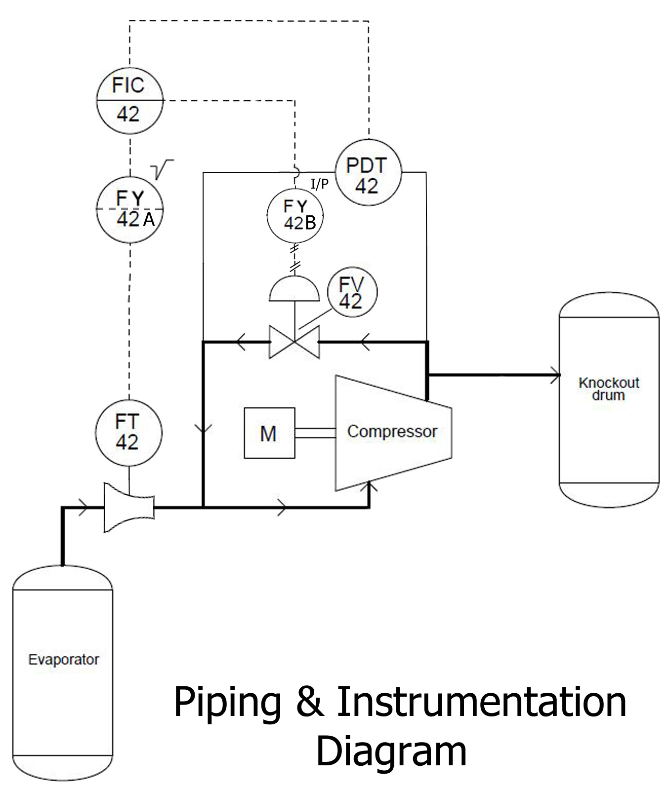
Piping And Instrumentation Diagrams (P&Ids) Use Specific Symbols To Show The Connectivity Of Equipment, Sensors, And Valves In A Control System.
This means if some system is shown on a single pfd, it may require multiple p&id sheets to show the same system on p&id. Function and purpose of p&ids. It’s most commonly used in the engineering field. Web p&id is a graphical representation of the actual process plant using various symbols that represent actual equipment.
A Through Knowledge Of The Information Presented In The Title Block, The Revision Block, The Notes And Legend, And The Drawing Grid Is Necessary Before A Drawing Can Be Read.
P&id (piping and instrumentation diagram or drawing) is a technical drawing used in process engineering. P&ids are used to develop guidelines and standards for facility operation. P&ids are foundational to the maintenance and modification of the process that it graphically represents. Visual paradigm's p&id tool features a handy diagram editor that allows you to draw p&id diagrams, industrial diagrams, and schematics quickly and easily.