Engineering Drawing Information Box
Engineering Drawing Information Box - Web detailed information about the drawing, such as who drew it and who approved it, is contained in a title block or information box. Engineering drawings use standardised language and symbols. Boiler house and chimney topics. “revision of engineering drawings and associated documents”. Web an engineering drawing is a visual representation that communicates the design, dimensions, and specifications of an object or assembly. Web any engineering drawing should show everything: Web engineering drawing title block. Web engineering drawing is a specialized form of communication that uses a strict set of symbols, standards, and perspectives to depict mechanical, electrical, or structural designs. An engineer border in visio 2016 is a predefined set of visual elements, such as a title block, scale, and north arrow, designed to improve technical drawings. Web an engineering drawing is a subcategory of technical drawings.
It is the universal “engineering technology language” in the world. In table 1 are shown the most widely used a and b series of the iso drawing sheet sizes, with a4 being the most popular size. Web according to iso 29845:2011, drawing is “technical information, given on an information carrier, graphically presented in accordance with agreed rules and usually to scale.” although engineers created the engineering drawings in the past by hand, today, they are primarily done in cad software like autodesk fusion 360. Web first, we will consider the sheet sizes, drawing format, title blocks, and other parameters of the drawing form. Graphics is a visual communications language that include images, text, and numeric information. The revision practices of this standard apply to any form of original drawing. Web more detailed production drawings may be produced based on the information given in an engineering drawing. If the isometric drawing can show all details and all dimensions on one drawing, it is ideal. Web an engineering drawing is a technical drawing that conveys any information required to manufacture a part that meets a customer’s specific needs. It offers a polished layout for engineering diagrams, promoting uniformity and clarity throughout designs.
Learn the ins and outs of engineering drawing standards, such as iso and ansi, which govern the symbols, abbreviations, and notations. The engineering drawing of a single part provides a visual representation of the structure, dimensions, tolerances, and other requirements of a part. Check the title block for basic information about the drawing. Graphics communications using engineering drawings and models is a clear and precise language with definite rules. Web the information block is often located at the bottom of engineering drawings. Web information on the person who created the drawing is usually contained in a title box. In table 1 are shown the most widely used a and b series of the iso drawing sheet sizes, with a4 being the most popular size. Common types of lines used include: Web first, we will consider the sheet sizes, drawing format, title blocks, and other parameters of the drawing form. Drawings have an information box or title block containing who drew the drawing, who approved it, units of dimensions, meaning of views, the title of the drawing and the drawing number.
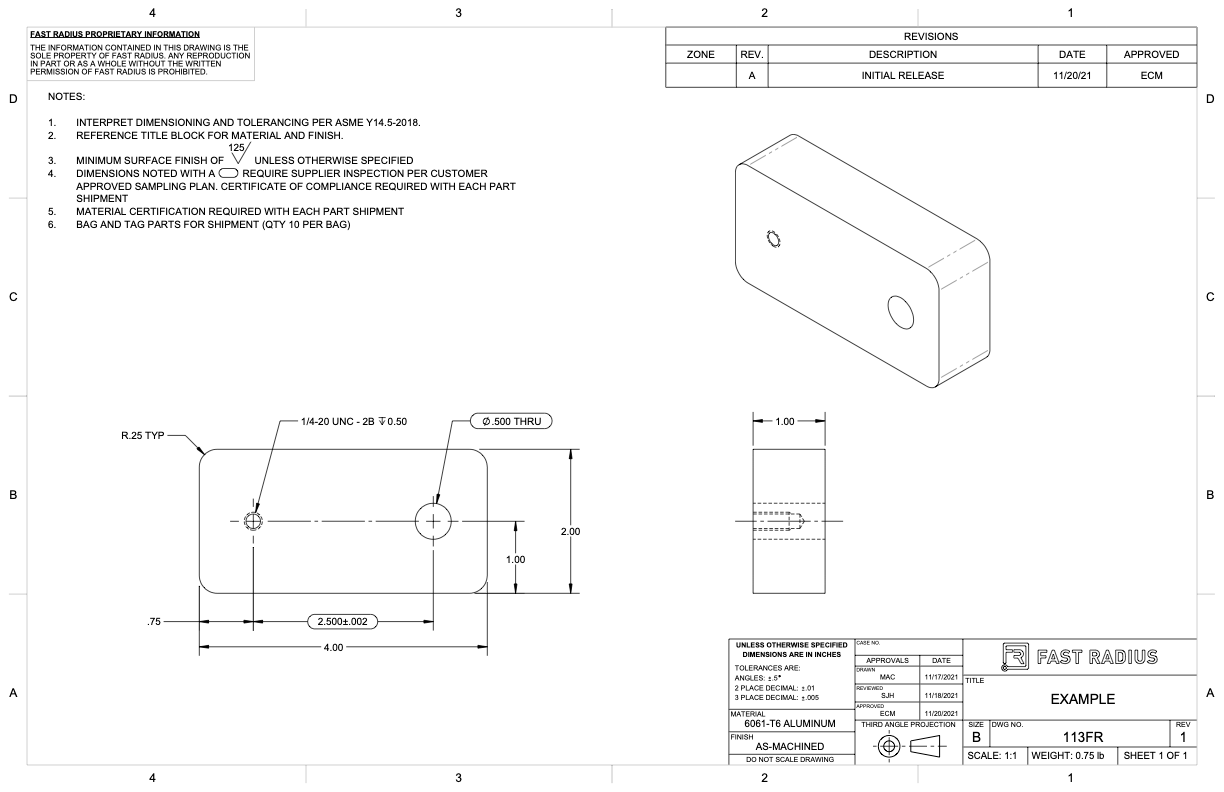
What to Include in Your Engineering Drawing Fast Radius
Common types of lines used include: The revision practices of this standard apply to any form of original drawing. Lines outline shapes, define edges, and convey different features. An engineer border in visio 2016 is a predefined set of visual elements, such as a title block, scale, and north arrow, designed to improve technical drawings. Web any engineering drawing should.

Standard Engineering Drawing Symbols Design Talk
These drawings are essentially the blueprints or plans for manufacturing a wide array of products and structures. In many cases, one simple part will require a series of drawings to fully explain its construction. • combustion combustion processes and their efficiency. It is the universal “engineering technology language” in the world. To know what information does it display and how.
2D Technical Drawings CNC Machining Service
Drawings have an information box or title block containing who drew the drawing, who approved it, units of dimensions, meaning of views, the title of the drawing and the drawing number. In many cases, one simple part will require a series of drawings to fully explain its construction. “revision of engineering drawings and associated documents”. It serves as a critical.

LEVERAGE ENGINEERING COMPANY Product Drawings
Common types of lines used include: The purpose is to convey all the information necessary for manufacturing a product or a part. A complete understanding of the object should be possible from the drawing. It serves as a critical tool for engineers, designers, and manufacturers to. Engineering drawings use standardised language and symbols.
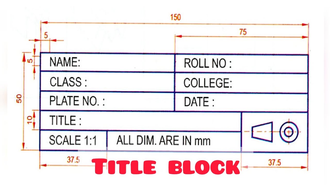
TITLE BLOCK in Technical drawing Engineering drawing Basic
The terms used in the table are clarified here: Correctly creating and reading engineering drawings is an essential ability for engineering technicians. Lines outline shapes, define edges, and convey different features. Web engineering drawing is a specialized form of communication that uses a strict set of symbols, standards, and perspectives to depict mechanical, electrical, or structural designs. Web engineering drawings.

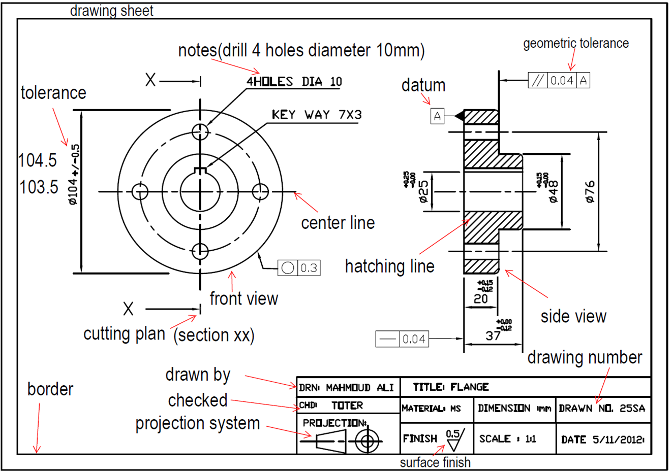
Engineering Drawing Basic Sheet layout , title Block , Notes
Learn the ins and outs of engineering drawing standards, such as iso and ansi, which govern the symbols, abbreviations, and notations. It serves as a critical tool for engineers, designers, and manufacturers to. Web any engineering drawing should show everything: The information contained in an engineering drawing is used to refine designs, develop prototypes, and construct and maintain objects. Drawings.
Engineer Drawing Template
Engineering drawings use standardised language and symbols. A complete understanding of the object should be possible from the drawing. Graphics communications using engineering drawings and models is a clear and precise language with definite rules. Web an engineering (or technical) drawing is a graphical representation of a part, assembly, system, or structure and it can be produced using freehand, mechanical.

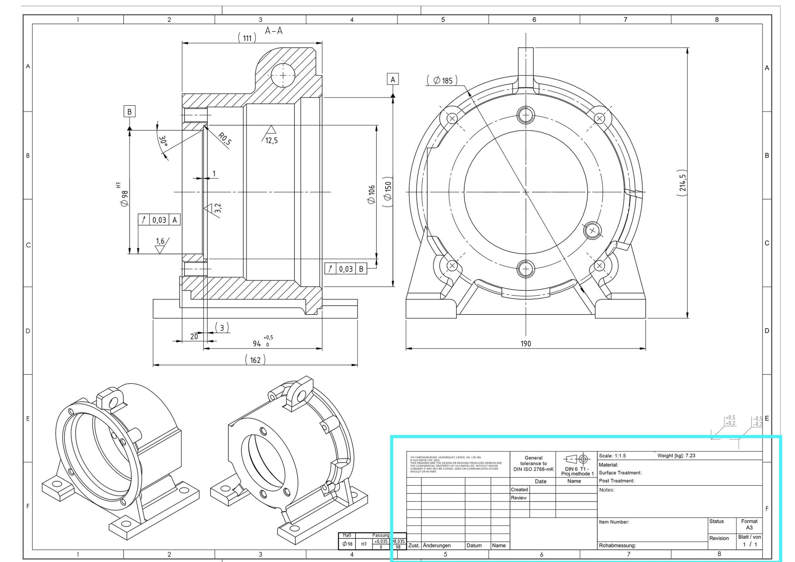
How to read iso drawings plmci
Web engineering drawing title block. To know what information does it display and how to adjust them, watch the foll. The information contained in an engineering drawing is used to refine designs, develop prototypes, and construct and maintain objects. Web engineering drawings (aka blueprints, prints, drawings, mechanical drawings) are a rich and specific outline that shows all the information and.

How to make a title box In engineering drawing, Title box in
Engineering drawings use standardised language and symbols. Properties of fuels like oil, gas, coal and wood and more. Web an engineering drawing is a subcategory of technical drawings. Web information on the person who created the drawing is usually contained in a title box. An engineer border in visio 2016 is a predefined set of visual elements, such as a.

How To Read Architectural Drawings Symbols The Architect
Web more detailed production drawings may be produced based on the information given in an engineering drawing. Web more detailed production drawings may be produced based on the information given in an engineering drawing. The purpose is to convey all the information necessary for manufacturing a product or a part. Check the title block for basic information about the drawing..
Graphics Is A Visual Communications Language That Include Images, Text, And Numeric Information.
Lines outline shapes, define edges, and convey different features. Common types of lines used include: Drawings have an information box or title block containing who drew the drawing, who approved it, units of dimensions, meaning of views, the title of the drawing and the drawing number. Web more detailed production drawings may be produced based on the information given in an engineering drawing.
An Engineer Border In Visio 2016 Is A Predefined Set Of Visual Elements, Such As A Title Block, Scale, And North Arrow, Designed To Improve Technical Drawings.
Through standardized language and symbols, engineering drawings communicate a designer’s exact requirements and expectations to manufacturers. Web an engineering drawing is a technical drawing that conveys any information required to manufacture a part that meets a customer’s specific needs. The title block of a drawing, usually located on the bottom or lower right hand corner, contains all the information necessary to identify the drawing and to verify its validity. Web the information block is often located at the bottom of engineering drawings.
Correctly Creating And Reading Engineering Drawings Is An Essential Ability For Engineering Technicians.
A title block is divided into several areas. It is the universal “engineering technology language” in the world. Web more detailed production drawings may be produced based on the information given in an engineering drawing. Web detailed information about the drawing, such as who drew it and who approved it, is contained in a title block or information box.
This Makes Understanding The Drawings Simple With Little To No Personal Interpretation Possibilities.
Properties of fuels like oil, gas, coal and wood and more. Web an engineering (or technical) drawing is a graphical representation of a part, assembly, system, or structure and it can be produced using freehand, mechanical tools, or computer methods. • drawing tools 2d and 3d engineering drawing tools. Web any engineering drawing should show everything: